13
TILLER
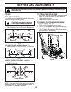
Fig. 16
Fig. 17
Fig. 19
CAUTION: Disconnect spark plug wire from spark plug and place wire where it cannot come into
contact with plug.
TINE ARRANGEMENT
Your outer tines can be assembled in several different ways
to suit your tilling or cultivating needs.
CAUTION: Tines are sharp. Wear gloves
or other protection when han dling tines.
tine_4
OUTER
TINE
INNER TINE
HAIRPIN CLIP
A
B
A
B
CLEVIS
PIN
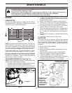
MID-WIDTH TILLING - 22" PATH (See Fig. 17)
• Assemble holes “A” in tine hubs to holes “C” in tine shaft.
tine_5
A
C
A
C
NORMAL TILLING - 24" PATH (See Fig. 16)
• Assemble holes “A” in tine hubs to holes “B” in tine shaft.
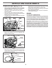
Fig. 18
NARROW TILLING/CULTIVATING - 13" PATH
(See Fig. 18)
• Remove outer tines.
tine_6
INNER TINES ONLY
NOTE: When reassembling outer tines, ensure right tine
assembly (marked “R”) and left tine assembly (marked “L”)
are mounted to correct side of tine shaft.
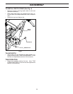
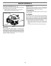
TO REMOVE CLUTCH HOUSING/ENGINE
ASSEMBLY (SEE FIG. 19)
• Drain engine oil and gasoline out of engine.
• Remove (5) carriage bolts and (5) lock nuts attaching
the clutch housing and tine shield to transmission.
• Remove clutch housing/engine assembly and lay on
ground (engine is upside down).
TO CHECK TINE OPERATION
• Start engine, tip tines off ground by pressing handles
down and engage tine control to start tine rotation.
• Verify tines spin properly.
• Allow tines to rotate for five minutes.
CARRIAGE
BOLTS
SERVICE AND ADJUSTMENTS


