


22
SERVICE AND ADJUSTMENTS
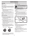
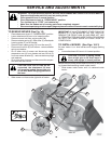
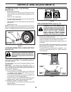
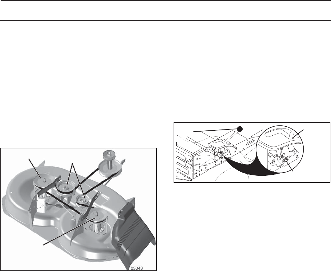
TO REPLACE MOWER BLADE DRIVE BELT
(See Fig. 26)
The mower blade drive belt may be replaced without tools.
Park the tractor on level surface. Engage parking brake.
BELT REMOVAL -
• Remove mower from tractor (See “TO REMOVE
MOW ER” in this section of manual).
• Work belt off both mandrel pulleys and idler pulleys.
• Pull belt away from mower.
BELT INSTALLATION -
• Work belt around both mandrel pulleys and idler pulleys.
• Make sure belt is in all pulley grooves and in side all
belt guides.
• Install mower (See "TO INSTALL MOWER" in this
section of manual).
FIG. 26
MANDREL
PULLEY
IDLER
PUL LEYS
MANDREL
PULLEY
TO CHECK BRAKE
If tractor requires more than five (5) feet to stop at highest
speed in high est gear on a level, dry concrete or paved
surface, then brake must be serviced.
You may also check brake by:
1. Park tractor on a level, dry concrete or paved surface,
depress clutch/brake pedal all the way down and en-
gage parking brake.
2. Place gear shift lever in neutral position.
The rear wheels must lock and skid when you try to manually
push the tractor forward. If the rear wheels rotate, then the
brake needs to be serviced. Contact a qualified service center.
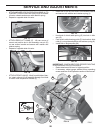
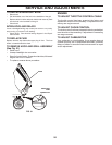
TRANSAXLE GEAR SHIFT LEVER NEU TRAL
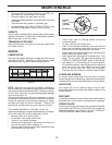
ADJUSTMENT (See Fig. 27)
The transaxle should be in neutral when the gear shift lever is
in neutral (lock gate) position. The adjustment is preset at the
factory; however, if adjustment is needed, proceed as follows:
• Make sure transaxle is in neutral.
NOTE: When the tractor rear wheels move freely, the
transaxle is in neutral.
• Loosen adjustment bolt in front of the right rear wheel.
• Position the gear shift lever in the neutral position.
• Tighten adjustment bolt securely.
NOTE: If additional clearance is needed to get to ad just ment
bolt, move mower deck height to the lowest position.
GEARSHIFT
LEVER
0
ADJUSTMENT
BOLT
NEUTRAL
LOCK
GATE
FIG. 27
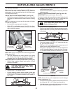
TO AD JUST STEER ING WHEEL ALIGN MENT
If steering wheel crossbars are not horizontal (left to right)
when wheels are positioned straight forward, remove steer-
ing wheel and reassemble per instructions in the Assembly
section of this manual.
FRONT WHEEL TOE-IN/CAMBER
Your new tractor front wheel toe-in and camber is set at the
factory and is normal. The front wheel toe-in and camber
are not adjustable. If damage has occurred to affect the
factory set front wheel toe-in or camber, contact a qualified
service center.