


6
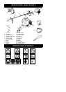
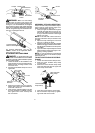
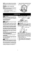
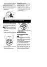
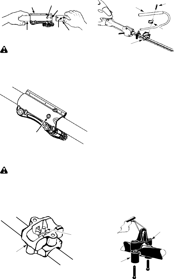
Coupler
Primary Hole
Upper
Shaft
Locking/
Release
Button
Attachment
Guide Recess
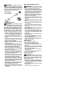
WARNING: Make sure the locking/
release button is locked in the primary hole
and theknob is securely tightened before o p -
erating the unit. All attach ments are des igned
to be used in the primary hole unless otherwise
stated in the applicable attachment instruction
manual. Using thewrong h ole couldlead toseri-
ous injury or damage t o the unit.
Locking/Release
Button in Primary Hole
For optional attachments, see the AS-
SEMBLY section of the applicable attach-
ment instruction manual.
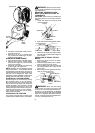
ATTA CH ING THE HANDLEBAR
DANGER: To avoid serious injury, the
barrier portion ofthe handlebar must beinstalled
as shown to provide a barrier between operator
and the spinning blade.
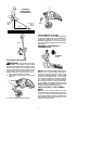
1. Locate the decal on the handlebar. This
decal includesan arrow.Position thehan-
dlebar with the mounting bracket at the
end of the arrow.
2. Align holeinhandlebar withpin onmount-
ing bracket.
Pin
Mounting
Bracket
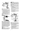
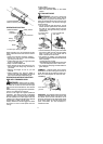
3. Position the bracket cover over the han-
dlebar. Again make sure the handlebar is
at the end of the arrow.
4. Insert screws and hand tighten only. Be
sure the handlebar is installed correctly;
then, tighten each screw securely with
the hex wrench.
Screw
Mounting
Bracket
Handlebar
Bracket Cover
ASSEMBLY OF SHOULDER STRAP
Proper shoulder strap and handlebar adjust-
ments must be made with the engine com-
pletely stopped before using unit.
1. Insertyour rightarmandhead thr oughthe
shoulder strap and allow it torest on your
left shoulder . Make sure the danger sign
is onyour back andthehook isto theright
side of your waist.
NOTE: A one-half twist is built in the shoul-
der strap to allow the strap to rest flat on the
shoulder.
2. Adjust the strap, allowing the hook to be
about 15 cm below the waist.
3. Fasten the strap hook to the clamp located
between the trigger handle and the handle-
bar clampbaseand lift t he toolto theoperat-
ing p osition.
4. Try on shoulderstrapandadjustfor f itand
balance before starting the engine or be-
ginning a cutting operation .
NOTE: It may be necessary to relocate the
shoulder strap clamp on the shaft for proper
balancing of unit.
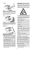
TO RELOCATE SHOULDER STRAP
CLAMP:
1. Loosen and rem ove both clamp screws.
2. Place the upper shoulder strap clamp
over the shaft.
3. Position the lower shoulder strap clamp
under the shaft and align the upper and
lower clamp screw holes.
Upper Shoulder
Strap Clamp
Screws
Lower Shoulder
Strap Clamp
4. Insert two screws into the screw holes.
5. Secure shoulder strap clamp by tighten-
ing screws with a hex wrench.