


10
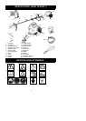
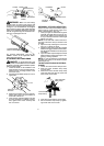
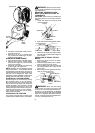
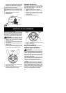
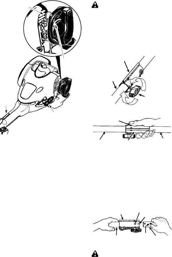
Throttle
lock--out
Primer Bulb
Start
Lever
Starter
Handle
5. Pull starter rope handle sharply until en-
gine starts and runs.
6. Allow unit to run for 10--15 seconds, then
fully squeeze the throttle trigger to disen-
gage the starting system.
STARTING A WARM ENGINE
1. Move ON/STOP switch t o the ON position.
2. Squeeze and hold the throttle trigger.
Keep throttle trigger fully squeezed until
engine runs smoothly.
3. Pull starter rope sharply while squeezing
throttle trigger until engine runs.
NOTE: Normally, the warm starting p rocedure
can be used within 5 -- 10 minutes after the unit
is turned STOP. If the unit sits for more than 10
minutes without being r un, itwillbe necessary t o
start the unit by following the steps under
STARTINGACOLDENGINEorfollowingthe
starting instruction steps shown on the unit.
STARTING A FLOODED ENGINE
Flooded engines can be started by placing
the ON/STOP switch in the ON position.
Move the start lever to the RUN position and
fully squeeze throttle trigger. Pull the starter
handle repeatedly while squeezing throttle
trigger untilenginestarts andruns. Thiscould
require pulling thestarter handle many times,
depending on how badly the unit is flooded.
If the unit still doesn’t start, refer t o TROU-
BLESHOOTING TABLE.
OPERATING THE COUPLER
This mode l is equipped with a coupler which
enables optional attachments to be installed.
WARNING: Always stop unitand dis-
connect spark plugbeforeremoving orinstal-
ling attachments.
REMOVING TRIMMER ATTACH-
MENT (OR OTHER OPTIONAL AT-
TACHMENTS)
CAUTION:
When removing or installing at-
tachments, place t he uniton a flat surface for
stability.
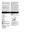
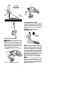
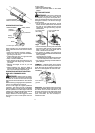
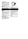
1. Loosen the coupler by turning the knob
counterclockwise.
Attachment
Coupler
Knob
LOOSEN
TIGHTEN
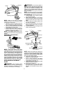
2. Press and hold the locking/release button.
Locking/Release
Button
Coupler
Upper Shaft
Attachment
3. While securely holdingtheengineandup-
per shaft, pull the attachment straight out
of the coupler.
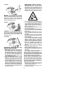
INSTALLING OPTIONAL ATTACH-
MENTS
1. Remove the shaft cap from the attach-
ment (if present).
2. Position locking/release button of attach-
ment into guide recess of coupler.
3. Push theattachment intothe coupleruntil
the locking/release button snaps into the
primary hole.
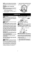
4. Before using theunit, t ightenthe knobse-
curely by turning clockwise.
Coupler
Primary Hole
Upper
Shaft
Locking/
Release
Button
Attachment
Guide Recess
WARNING: Make sure the locking/
release button is locked in the primary hole
and theknob is securely tightened before op-
erating the unit. Al l attachments a r e de signed
to be used in the primary hole unless o therwise
stated in the applicable attachment instruction
manual. Using the w rong h ole couldlead toseri-
ous inj ury or d amag e t o t he u nit.