


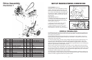

SET UP INSTRUCTIONS
UNPACKING
Do not attempt to lift the tiller from the carton.
After opening the top, cut all four corners and lay
the sides at on the oor or working space. Take
out all unassembled parts, bag of parts, and pro-
tective packing. Be careful not to kink the control
cables.
DEFINITION OF DIRECTIONS
As used throughout this manual, the following
denitions apply: “Right” and “Left” refer to the
operator’s right and left when standing behind the
machine in the normal operating position. “For-
ward” and “Rearward” likewise to directions from
the viewpoint of the operator.
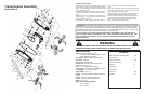
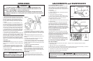
ASSEMBLY OF HANDLE BARS (Figures 2 & 3)
1. Attach the lower end of the handle bars to the
rear of the chassis using four bolts, lock wash-
ers, and nuts supplied. Assemble nuts but do not
tighten. Note that the lower belt cover bracket
goes under the chassis on the left rear handle
bar bolt.
2. Assemble the handle bar support brackets to
the transmission. Note the location of the clutch
cable guide. Assemble nuts but do not tighten.
3. Assemble the Handle Panel to the handle bars
and supports. Note the location of the clutch
cable guide.
4. Tighten all bolts and nuts.
5. Assemble the throttle control to the underside
of the panel. Secure the cable to the left handle
bar with the clip supplied.
6. Assemble the clutch spring to the clutch le-
ver on the handle bar. Crimp lightly so it cannot
come off.
7. Route the loop in the end of the clutch cable
down through the two cable guides and attach it
level on the idler arm weldment. Attach the chain
on the other end to the spring on the clutch lever.
Select a loop that will stretch the spring slightly
when the clutch lever is pulled against the handle
bar.
8. With the throttle control in the “OFF” position
and the clutch lever released, pull the engine
starter rope several times to be sure that the tines
do not turn.
Figure 2
Figure 3
IMPORTANT
ENGINE IS SHIPPED FROM
FACTORY WITHOUT OIL. DO
NOT START ENGINE WITHOUT
ADDING OIL.
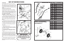
Ref Part Qty Description
1 130670 1 Rear Support Assembly
3 400265 1 Screw, 3/8” - 16 x 1 1/2
8 162034 1 Wheel Yoke Assembly
13 162031 2 Wheel
14 359330 2 Bolt, Wheel
16 444721 3 3/8” Center Locknut
18 460312 2 Hairpin
19 461466 2 Pin, 3/8” x 2 1/8” Clevis
21 336685 1 Drag Stake
Hitch Assembly
Illustration 2
Ref. Part Qty Description
1 162007 1 Throttle Control Assembly
2 336677 1 Support LH
3 336676 1 Support RH
4 130698 1 RH Handle Assembly
5 313786 2 Grip
6 130699 1 LH Handle Assembly
7 130731 1 Handle Cross Brace
8 400186 2 Screw 5/16 - 18 x 1” Hex
9 446136 4 Lockwasher 5/16 Heavy
10 443106 4 Nut, 5/16 - 18 Hex
11 402014 2 #10 x 3/8” Slot Tapping Scr.
14 162029 1 Cable and Chain Assembly
15 359346 1 Clutch Locking Pin
16 359359 1 Spring
17 359327 1 Spring
18 359326 1 Clip
19 359345 1 Pin
20 336683 1 Lever
21 400208 2 5/16 x 18 x 1 3/4 Hex Cap
Handle Bar Assembly -- Illustration 2
4 9