


13
106813
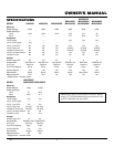
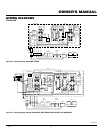
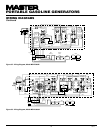
OWNER’S MANUAL
RESET
TEST
120 VOLTS
RESET
240 VOLTS
OFF
Auto-Idle
ON
RESET
RESET
RESET
ENM
00000005
HOURS 1/10
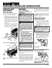
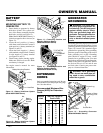
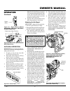
Choke Lever (Open Position)
Figure 25 - Choke Lever Opened (Model
MGH7000D Shown)
OPERATION
Continued
HONDA
OFF
ON
START
ENGINE SW
CIRCUIT
BREAKER
ON/push OFF
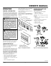
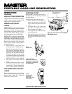
Figure 24 - Engine Switch (Models
MGH5000DIE, MGH7000D, MGH7000DI,
and MGH10000A Only)
Engine
Switch
AUTO-IDLE OPERATION
IMPORTANT:
Never start engine with elec-
trical loads connected. Start engine before
adding electrical loads.
1. If engine is cold, turn the Auto-Idle
switch OFF (see Figure 26).
2. Start engine. Allow engine to warm up
with no load for five minutes.
3. Turn Auto-Idle switch ON. Engine will
slow to idle speed. Engine idle speed
is preset. Idle speed adjustment should
not be necessary.
4. Operate generator according to speci-
fications outlined in owner's manual.
5. Engine will automatically increase to
normal operating speed when you plug
load into any generator outlet.
WARNING: Always set the idle
speed before turning on the Auto-
Idle. If idle speed is not set, the
larger resistor on the control board
may become hot. Heat from the
resistor may damage the protec-
tive coating on the control board.
Note:
The 250 Volt/50 Amp receptacle
is not connected through the Auto-Idle
circuit. The Auto-Idle switch must be
turned off to get full power out of this
receptacle (see Figure 26).
6. The Auto-Idle system should be turned
OFF when generator is shut down.
Adjusting the Idle Speed
IMPORTANT:
Adjust the idle speed only:
• If the idle speed becomes too high.
• If the engine idle speed will not regulate (en-
gine idles and speeds up again and again).
1. Turn Auto-Idle switch OFF. Start en-
gine. Allow engine to warm up with no
load for five minutes.
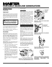
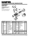
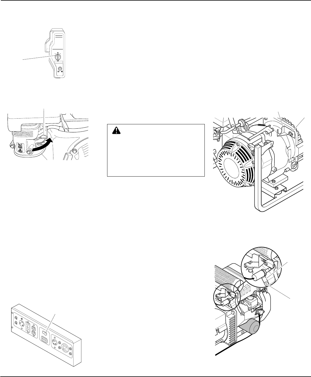
Solenoid
Mounting
Bracket
Bolt
OFF
ENGINE
Solenoid Mounting
Bracket
M8 Nut
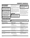
Figure 27 - Solenoid Bracket Location,
Models MGH4000CI, MGH5000DI,
MGH5000DIE, MGH6000DI, and
MGH7000D Only
Figure 28 - Solenoid Bracket Location,
Model MGH10000A OnlyFigure 26 - Control Panel
Auto-Idle Switch
2. Remove engine linkage cover
(Models MGH4000CI, MGH5000DI,
MGH5000DIE, MGH6000DI, and
MGH7000DI).
3. Push plunger into solenoid body to manu-
ally engage solenoid and set idle speed.
4. Loosen the M8 nut that holds the sole-
noid mounting bracket to the generator
(Models MGH4000CI, MGH5000DI,
MGH5000DIE, MGH6000DI, and
MGH7000DI. See Figure 27). Do not
loosen bolt that holds the solenoid
mounting bracket to the generator on
Model MGH10000A (see Figure 28).
5. Slowly pull solenoid bracket away from
engine (on Model MGH10000A this will
require bending the bracket slightly).
6. With a volt meter, check the no-load
output voltage at the 120-volt duplex
receptacle. At proper idle speed (2680
minimum RPM) the meter should read
50-60 volts. Lower settings will cause
the Auto-Idle to not operate properly.
7. After reaching proper idle speed,
tighten M8 nut to secure solenoid
mounting bracket (Models
MGH4000CI, MGH5000DI,
MGH5000DIE, MGH6000DI, and
MGH7000DI (see Figure 27).
8. Turn Auto-Idle switch ON. Make sure
solenoid is engaged. When engaged, the
punger is pulled back into the solenoid.
9. If the engine speed is too slow, the en-
gine will want to "hunt" or speed up
and slow down repeatedly. When this
occurs, increase engine speed by adjust-
ing throttle stop screw on carburetor
(refer to Carburetor Adjustment in
Honda Engine Manual).
10. Replace the engine linkage cover
(Models MGH4000CI, MGH5000DI,
MGH5000DIE, MGH6000DI, and
MGH7000DI).