


17
Snowthrower Installation
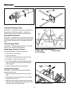
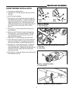
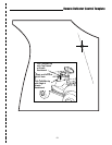
Figure 21. Attach Drive Shaft
A. Locking Collar
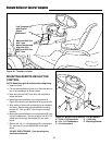
SNOWTHROWER INSTALLATION
1. Fully lower the attachment lift.
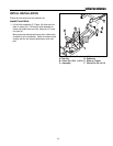
2. See Figure 19. Pull the shot pins (B) back and lock-
ing them.
3. Set PTO shaft on bracket.
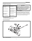
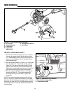
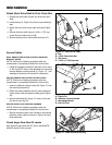
4. See Figure 20. Drive the tractor push bar under the
snowthrower hitch point (B). The dozer snowthrower
hitch points (B) need to line up side to side with the
edges of the push bar (A). The snowthrower hitch
points (B) will hang from the top edge of the push bar
(A). Slowly lift the snowthrower 1/2 inch off the
ground.
5. See Figure 19. Place snowthrower shot pins (A) in
closed position.
6. Make sure that PTO shaft is aligned with reduction
box input shaft. This is done to prevent PTO shaft
from interfering with connection point and to help
align the shaft for hookup.
7. Stop engine, lock parking brake and remove key.
8. Check that shot pins (Figure 19) are fully seated into
push bar (A, Figure 20). If the shot pins do seat all
the way in the Closed / In position repeat steps 1-8.
9. See Figure 21. Attach the drive shaft. Pull back on
the locking collar (A) and slide the drive shaft fully
onto the snowthrower. Release the locking collar and
pull back on the drive shaft until the locking collar
locks onto the shaft.
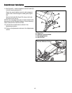
10.See Figure 22. Attach the electric chute rotator to the
tractor attachment plug.
Figure 22. Attachment Electrical Connection
Figure 20. Attaching the Snowthrower to the Hitch
A. Push Bar
B. Hitch Point
A
B
Closed
(In)
Open
(Out)
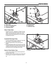
Figure 19. Shot Pins
A. Shot Pin (Closed)
B. Shot Pin (Open)
Lock
A
B
A