


15
Initial Installation
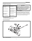
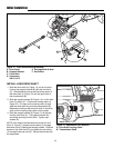
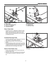
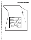
Figure 14. Discharge Chute Assembly
A. Discharge Chute
B. Plastite Screw
C. Hold-Down Plate
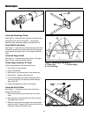
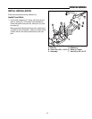
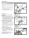
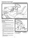
Mount Cable Guide
1. Using the 5/16-18 x 1 capscrew (C, Figure 13), lock-
washer, and nut (D) provided and the 5/16-18 x 5/8
taptite screw (B) securing the rotator motor mount
bracket, secure the cable guide (A) to the snowthrow-
er assembly as shown.
A
B
C
Figure 13. Secure Cable Guide
A. Cable Guide
B. 5/16-18 x 5/8 Taptite Screw
C. 5/16-18 x 1 Capscrew
D. Lockwasher & Nut
A
B
C
D
Assemble Discharge Chute
1. Locate the discharge chute (A, Figure 14), three hold-
down plates (C), and plastite screws (B).
2. Coat the top and bottom of the chute ring with
grease.
3. Install the discharge chute onto the chute ring, facing
it straight forward over the auger housing, and secure
it using the hold-down plates (C) and plastite screws
(B). Be careful not to over-tighten the screws.
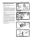
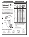
Electric Chute Rotator Gear
1. Loosen the two taptite screws (A) securing the elec-
tric spout rotator motor.
2. Adjust the motor so that it meshes with the discharge
chute ring gear and tighten the adjustment screws
(A).
Figure 15. Discharge Chute Motor Adjustment
A. Screws
A
A