


5
FUNCTIONAL DESCRIPTION
CAUTION:
• Always be sure that the tool is switched off and
unplugged before adjusting or checking function on the
tool.
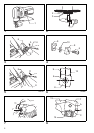
Switch action (Fig. 1)
CAUTION:
• Before plugging in the tool, always check to see that
the slide switch actuates properly and returns to the
“OFF” position when the rear of the slide switch is
depressed.
• Switch can be locked in “ON” position for ease of oper-
ator comfort during extended use. Apply caution when
locking tool in “ON” position and maintain firm grasp on
tool.
To start the tool, slide the slide switch toward the “I (ON)”
position. For continuous operation, press the front of the
slide switch to lock it.
To stop the tool, press the rear of the slide switch, then
slide it toward the “O (OFF)” position.
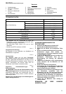
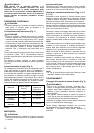
Permissible shearing thickness (Fig. 2)
The groove on the yoke serves as a thickness gauge for
shearing mild or stainless steel plate. If the material fits
within the groove, it is shearable.
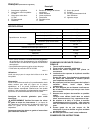
The thickness of materials to be sheared depends upon
the type (strength) of the material. The maximum shear-
ing thickness is indicated in the table below in terms of
various materials. Attempting to shear materials thicker
than indicated will result in tool breakdown and/or possi-
ble injury. Keep within the thickness shown in the table.
006425
ASSEMBLY
CAUTION:
• Always be sure that the tool is switched off and
unplugged before carrying out any work on the tool.
Blade inspection
Before using the tool, check the blades for wear. Dull,
worn blades will result in poor shearing action, and the
service life of the tool will be shortened.
Rotating or replacing blades (Fig. 3, 4, 5, 6, 7 & 8)
Both the upper and lower blades have four cutting edges
on each side (the front and back). When the cutting edge
becomes dull, rotate both the upper and the lower blades
90° to expose new cutting edges.
When all eight edges are dull on both the upper and
lower blades, replace both blades with new ones. Each
time blades are rotated or replaced, proceed as follows.
Remove the blade securing bolts with the hex wrench
provided and then rotate or replace the blades.
Some tools have one washer between the upper blade
and the blade holder. When the tool has the washer, be
sure to use the thin washer when reassembling.
NOTE:
• No thin washers are used for the lower blade.
Install the upper blade and tighten the upper blade secur-
ing bolt with the hex wrench. Press up on the upper
blade while tightening it.
After securing the upper blade, be sure that there is no
gap left between the upper blade and the beveled sur-
face of the blade holder.
When installing the lower blade onto the yoke, the lower
blade should be pressed against the yoke so as to be
contacting the beveled portions A and B of the yoke and
the tip C of the lower blade positioning screw while you
tighten the lower blade securing bolt. There must be no
clearance between A, B and C during installation.
NOTE:
• The lower blade positioning screw is factory-assem-
bled. Do not tamper with it.
OPERATION
Holding material and shearing method (Fig. 9)
WARNING:
• Before operating the tool, be sure to firmly tighten the
upper blade securing bolt and the lower blade securing
bolt. Loosen bolts may cause blades coming off, result-
ing in a serious injury.
• When cutting, always place the shear on the workpiece
so that the material cut away is positioned on the right
side to the operator.
The materials for cutting should be fastened to the work-
bench by means of workholders.
Always hold the tool firmly with one hand on housing. Do
not touch the metal part.
Keep the shear moving parallel with the material.
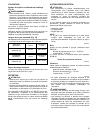
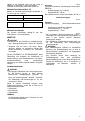
Maximum cutting width (Fig. 10)
Stay within the specified maximum cutting width (A):
Case of length 1,800 mm.
006430
Material
Tensile Strength
(N/mm
2
)
Max. cutting
thickness (mm)
Mild steel (A) 400 1.6 (16 ga)
Hard steel (B) 600 1.2 (18 ga)
Stainless steel 800 0.8 (22 ga)
Aluminum plate 200 2.5 (13 ga)
Mild steel (thickness) 1.6 mm Under 1.2 mm
Max. cutting width (A) 100 mm No limit
Stainless (thickness) 1.2 mm Under 1.0 mm
Max. cutting width (A) 80 mm No limit