


7
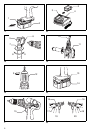
Switch action (Fig. 7)
CAUTION:
Before inserting the battery cartridge into the tool, always
check to see that the switch trigger actuates properly and
returns to the “OFF” position when released.
To start the tool, simply pull the trigger. Tool speed is
increased by increasing pressure on the trigger. Release
the trigger to stop.
Reversing switch action (Fig. 8)
CAUTION:
• Always check the direction of rotation before operation.
• Use the reversing switch only after the tool comes to a
complete stop. Changing the direction of rotation
before the tool stops may damage the tool.
• When not operating the tool, always set the reversing
switch lever to the neutral position.
This tool has a reversing switch to change the direction of
rotation. Depress the reversing switch lever from the A
side for forward rotation or from the B side for reverse
rotation. When the switch lever is in between (the neutral
position), the switch trigger cannot be pulled.
Speed change (Fig. 9)
To change the speed, first switch off the tool and then
slide the speed change lever to the “II” side for high
speed or “I” side for low speed. Be sure that the speed
change lever is set to the correct position before opera-
tion. Use the right speed for your job.
CAUTION:
• Always set the speed change lever fully to the correct
position. If you operate the tool with the speed change
lever positioned half-way between the “I” side and “II”
side, the tool may be damaged.
• Do not use the speed change lever while the tool is run-
ning. The tool may be damaged.
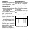
Selecting the action mode (Fig. 10)
This tool employs an action mode changing ring. Select
one of the three modes suitable for your work needs by
using this ring. For rotation only, turn the ring so that the
arrow on the tool body points toward the
M mark on the
ring. For rotation with hammering, turn the ring so that
the arrow points toward the
X on the ring. For screw-
driving (rotation with clutch), turn the ring so that the
arrow points toward the
U mark on the ring.
CAUTION:
Always set the ring correctly to your desired mode mark.
If you operate the tool with the ring positioned half-way
between the mode marks, the tool may be damaged.
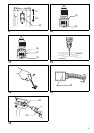
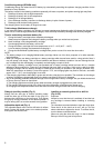
Adjusting the fastening torque (Fig. 11)
The fastening torque can be adjusted in 16 steps by turn-
ing the adjusting ring so that its graduations are aligned
with the arrow on the tool body. The fastening torque is
minimum when the number 1 is aligned with the arrow,
and maximum when thenumber 16 is aligned with the
arrow.
Before actual operation, drive a trial screw into your
material or a piece of duplicate material to determine
which torque level is required for a particular application.
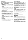
Screwdriving operation (Fig. 12)
First, turn the action mode changing ring so that the
arrow on the tool body points to the
U marking. Adjust
the adjusting ring to the proper torque level for your work.
Then proceed as follows.
Place the point of the driver bit in the screw head and
apply pressure to the tool. Start the tool slowly and then
increase the speed gradually. Release the trigger as
soon as the clutch cuts in.
NOTE:
• Make sure that the driver bit is inserted straight in the
screw head, or the screw and/or bit may be damaged.
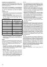
• When driving wood screws, predrill pilot holes to make
driving easier and to prevent splitting of the workpiece.
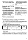
See the chart below.
• If the tool is operated continuously until the battery car-
tridge has discharged, allow the tool to rest for 15 min-
utes before proceeding with a fresh battery.
Nominal diameter
of wood screw (mm)
Recommended size
of pilot hole (mm)
3.1 2.0 – 2.2
3.5 2.2 – 2.5
3.8 2.5 – 2.8
4.5 2.9 – 3.2
4.8 3.1 – 3.4
5.1 3.3 – 3.6
5.5 3.6 – 3.9
5.8 4.0 – 4.2
6.1 4.2 – 4.4