


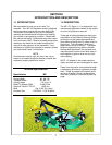
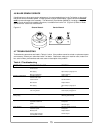
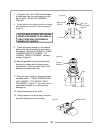
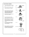


BLADE SPINDLE ASSEMBLY
1. Press the outer bearing in the housing
until the bearing bottoms out. (Figure
8)
2. Press the lower outer bearing on the
shaft until it bottom out. (Figure 9)
3. Place the outer shaft and lower bear-
ing through the hub into the top outer
bearing. Press together until both
outer bearing races bottom out on
housing and shaft. (Figure 10)
4. Press the inner bearing into the top of
the outer shaft. (Figure 10)
5. Thread the blade carrier and the
sheave on the outer shaft. (Figure 11)
6. Attach the blade carrier wrench to the
blade carrier (Figure 5). Put the spin-
dle in the upright position and place
the blade carrier wrench in a vise and
secure it.
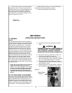
7. Use the sheave wrench (Figure 6).
Turn counterclockwise and tighten
sheave to 200 ft.lbs.
8. Remove spindle from vise. Place the
sheave wrench in the vise and secure
it. (Figure 12) Place the spindle
sheave on the sheave wrench and
Figure 8
Figure 9
Figure 10
Figure 11
Figure 12
Housing
Top Outer
Bearing
Shaft
Lower Outer
Bearing
Sheave
Blade
Carrier
Sheave Wrench
21