


D-1
MAINTENANCE
D-1
SAFETY PRECAUTIONS
ELECTRIC SHOCK can kill.
• Only qualified personnel should per-
form this maintenance.
• Turn the input power OFF at the dis-
connect switch or fuse box before
working on this equipment.
• Do not touch electrically hot parts.
------------------------------------------------------------------------
To avoid receiving a high frequency shock, keep
the TIG torch and cables in good condition.
------------------------------------------------------------------------
ROUTINE AND PERIODIC MAINTENANCE
1. Disconnect power supply lines to machine before
performing periodic maintenance.
2. Periodically clean the inside of the machine with a
low pressure air system. Be sure to clean the fol-
lowing components thoroughly.
• Main Transformer
• Electrode/Gas Output Receptacle
• Polarity Switch
• Rectifier Assembly
• Arc Starter/Spark Gap Assembly
• PC Boards
• Fan Blades
3. Inspect welder output and control cables for fraying,
cuts, and bare spots.
4. Keep TIG torch and cables in good condition.
5. Clean air louvers to ensure proper air flow and cool-
ing.
6. The fan motor has sealed ball bearings which
require no maintenance.
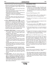
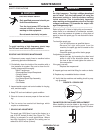
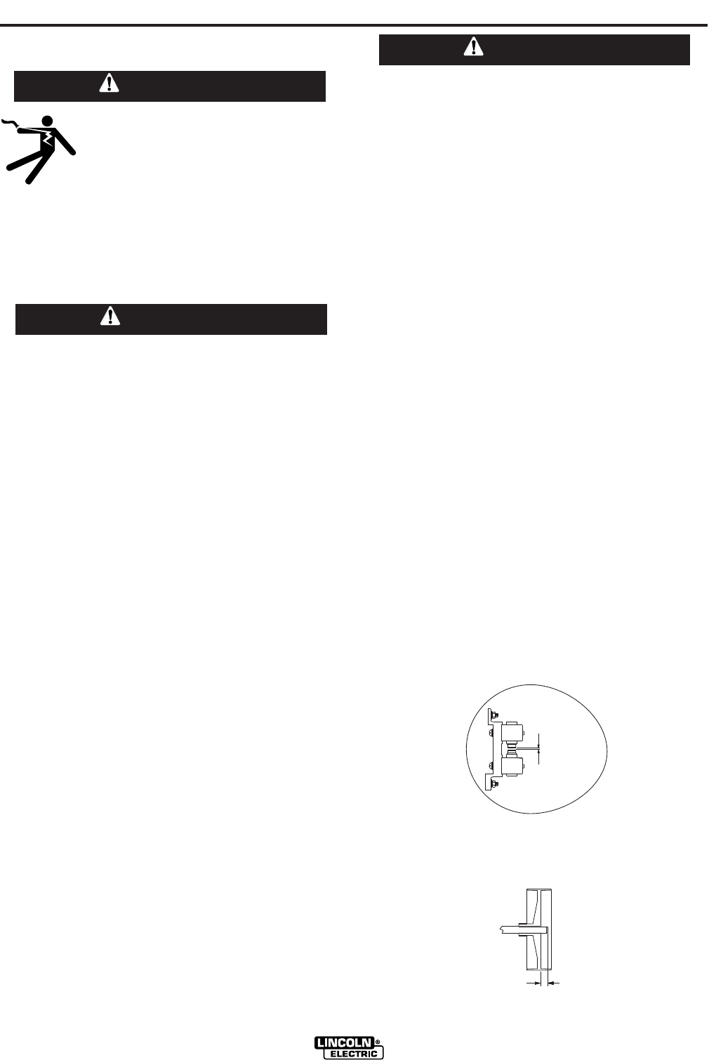
7. SPARK GAP ADJUSTMENT
The spark gap .020(.5mm) is set at the factory to a
gap of 0.015 inches (0.4mm) See Figure D.1. This
setting is adequate for most applications. Where
less high frequency is desired, the setting can be
reduced to 0.015 inches (0.4mm).
Use extreme caution when working with circuit of
the high frequency. The high voltages developed
can be lethal. Turn the input power off using the
disconnect switch or fuse box before working
inside machine. This is particularly important
when working on the secondary circuit of the high
voltage transformer (T3) because the output volt-
age is dangerously high.
-----------------------------------------------------------------------
Refer to figure D.1. Note in highly dirty environments
where there is an abundance of conductive contami-
nants, use a low pressure air stream or a firm piece of
paper to clean the spark gap. Do not disturb the facto-
ry setting.
To check the spark gap:
- Turn off input power as specified above.
- Remove the right side panel from the
machine, the spark gap box is located on the
lower right side.
- Check the spark gap with a feeler gauge.
If adjustment is needed:
- Adjust the gap by loosening the allen head
screw in one of the aluminum blocks, near
the front of the unit and tighten the screw in
the new position.
If the gap is correct:
- Replace the wraparound.
8. Inspect gas hose and inlet fitting for cracks or leaks.
9. Replace any unreadable labels or decals.
10. Verify that the machine and welding circuit is prop-
erly grounded.
FIGURE D.1 SPARK GAP
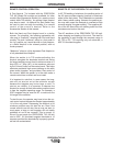
FAN MOTOR OR FAN BLADE REPLACEMENT
When installing a new fan blade or fan motor be sure
to maintain proper shaft spacing per Figure D.2 below.
PRECISION TIG 185
WARNING
WARNING
WARNING
.020 Spark Gap
.020 Spark Gap
FIGURE D.2
.30