


A-4
INSTALLATION
PRECISION TIG 185
A-4
The high frequency generator, being similar to a radio
transmitter, may cause radio, TV and electronic equip-
ment interference problems. These problems may be
the result of radiated interference. Proper grounding
methods can reduce or eliminate radiated interfer-
ence.
Radiated interference can develop in the following
four ways:
1. Direct interference radiated from the welder.
2. Direct interference radiated from the welding leads.
3. Direct interference radiated from feedback into the
power lines.
4. Interference from re-radiation of “pickup” by
ungrounded metallic objects.
Keeping these contributing factors in mind, installing
equipment per the following instructions should mini-
mize problems.
1. Keep the welder power supply lines as short as
possible. Input leads within 50 feet (15.2m) of the
welder should be enclosed in rigid metallic conduit
or equivalent shielding. There should be good elec-
trical contact between this conduit and the welder
case ground. Both ends of the conduit should be
connected to a driven ground and the entire length
should be continuous.
2. Keep the work and electrode leads as short as pos-
sible and as close together as possible. Lengths
should not exceed 25 ft (7.6m). Tape the leads
together when practical.
3. Be sure the torch and work cable rubber coverings
are free of cuts and cracks that allow high frequen-
cy leakage.
4. Keep the torch in good repair and all connections
tight to reduce high frequency leakage.
5. The work piece must be connected to an earth
ground close to the work clamp, using one of the
following methods:
a) A metal underground water pipe in direct contact
with the earth for ten feet or more.
b) A 3/4” (19mm) galvanized pipe or a 5/8”
(16mm)solid galvanized iron, steel or copper rod
driven at least eight feet into the ground.
The ground should be securely made and the ground-
ing cable should be as short as possible using cable
of the same size as the work cable, or larger.
Grounding to the building frame electrical conduit or
along pipe system can result in re-radiation, effectively
making these members radiating antennas.
6. Keep cover and all screws securely in place.
7. Electrical conductors within 50 ft (15.2m) of the
welder should be enclosed in grounded rigid metal-
lic conduit or equivalent shielding, wherever possi-
ble. Flexible metallic conduit is generally not suit-
able.
8. When the welder is enclosed in a metal building,the
metal building should be connected to several good
earth driven electrical grounds (as in 5 (b) above)
around the periphery of the building.
Failure to observe these recommended installation
procedures can cause radio or TV and electronic
equipment interference problems and result in unsat-
isfactory welding performance resulting from lost high
frequency power.
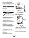
INPUT CONNECTIONS
Be sure the voltage, phase, and frequency of the input
power is as specified on the rating plate, located on
the rear of the machine.
208/230 volt models have a NEMA 6-50P plug
attached to the #8-3 input power cord and a NEMA 6 -
50R receptacle is included with the Ready-Pak mod-
els. Other voltage models have an input power cord
but no plug or receptacle.
Have a qualified electrician provide input power sup-
ply to the receptacle or cord in accordance with all
local and national electrical codes. Use a single phase
line or one phase of a two or three phase line. Choose
an input and grounding wire size according to local or
national codes. Refer to the Technical
Specifications page at the beginning of this section.
Fuse the input circuit with the recommended super lag
fuses or delay type
1
circuit breakers. Using fuses or
circuit breakers smaller than recommended may result
in “nuisance” shut-offs from welder inrush currents
even if not welding at high currents.
1
Also called “inverse time” or “thermal/magnetic” circuit breakers;
circuit breakers which have a delay in tripping action that decreases
as the magnitude of the current increases.