


$(*%(%&(*%$
5CEB5D81D1>I5<53DB931<5AE9@=5>D@<E77549>D?
D8575>5B1D?BWC@?G5BB535@D13<5C31>G9D8
CD1>41PF?<D1751>41P6B5AE5>3IF1B91
D9?>)?=55<53DB?>9345F935C31>>?D25@?G5B54
2ID85+""%O(565BD?*12<5
"*(",+)-**+""%O
9>D85$)*""*%$C53D9?>?6D89C=1>E
1<
------------------------------------------------------------------------
$("$%(#*%$
The BULLDOG™ 5500 generator is rated at 4000
continuous watts (5500 surge watts). It provides both
120 volt and 240 volt power. You can draw up to 20
amps from either side of the 120 volt duplex recepta-
cle, but no more than 33.3 amps from both sides at
once. Up to 16.7 amps can be drawn from the single
240 volt receptacle.
Electrical loads in watts are approximately calculated
by multiplying the voltage rating of the load by the
number of amps it draws. (This information is given
on the load device nameplate.) For example, a device
rated 120 volts, 2 amps will need 240 watts of power
(120 x 2 = 240).
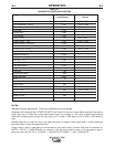
You can use Table B.1, GENERATOR POWER
APPLICATIONS, to determine the wattage require-
ments of the most common types of loads you can
power with the BULLDOG™ 5500. Be sure to read
the notes at the bottom of the table.
*%+)*+""%O)$+."(/
&%-()+&&"/
1. Start the gasoline engine. See $$%&(
*%$ in this section of the manual and the engine
owner’s manual.
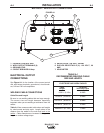
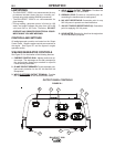
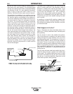
2. Set the current control dial on the output control
panel to “GENERATOR”. See Figure B.1.
3. Plug the load(s) into the appropriate 120 volt or
240 volt power receptacle.
$%* During welding, the maximum generator out-
put for auxiliary loads is 100 watts.
$%* You can supply multiple loads as long as the
total load does not exceed 5,500 surge watts
or 4,000 Continuous watts. Be sure to start
the largest loads first.
%&(*%$
)*%&&$*$$
1. Remove all welding and generator power loads
and let the engine cool by running it for several
minutes.
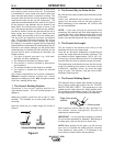
2. Stop the engine by placing the “ON/OFF” switch in
the “OFF”(%) position.
3. Close the fuel shutoff valve.
<?C5D856E5<F1<F5G85>D85=1389>59CDB1>C
@?BD54D?@B5F5>D6E5<<51;1756B?=D8531B2EB5D?B
?B<?>7@5B9?4C?6CD?B175DEB>?66D856E5<C8ED
?66F1<F51>4<5DD855>79>5BE>E>D9<D85B59C>?
=?B56E5<9>D85<9>5+C516E5<1449D9F5CE381C
)D19<D?=9>9=9J56E5<7E=45@?C9DC
------------------------------------------------------------------------
(+$$$*$$
The engine is set at the factory to run at high idle
speed when not under load. You should not adjust
this setting yourself.
(!$&(%
The engine will use a greater amount of oil during its
“break-in” period. Check the oil frequently during
break-in. For more details, see the MAINTENANCE
section in the engine owner’s manual.
EB9>72B51;9>D85E>9DC8?E<425CE2:53D54D?
=?45B1D5<?14C56?B5CD?@@9>7D855>79>5
B5=?F51<<<?14C1>41<<?GD855>79>5D?3??<C5F
5B1<=9>ED5C
------------------------------------------------------------------------
"%-%")$)$
This engine has a built in sensor which responds to
low oil level (not pressure). When activated, the syst-
tem will shut the engine down. The engine will not
restart untill sufficient oil is added. Check oil level fre-
quently and add oil as required to the full mark on the
dipstick. %$%*%,(""
+""%O
-($$
+*%$
+*%$