


10
RTA10 & RTA15 Series Rotary Tillers 311-252M
5/05/06
Land Pride
Section 1 Assembly and Set-Up
Table of Contents
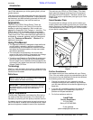
Driveline Installation
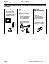
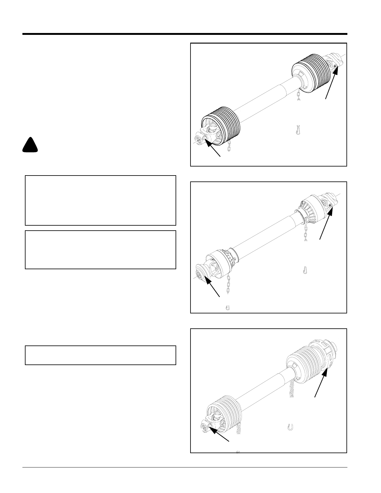
Refer to Figure 1-3, Figure 1-4 and Figure 1-5
The tiller driveline is coupled to the tractor and implement
shafts with either push pin couplers, pull collar couplers
or a combination of both and with either a shear bolt or
slip clutch on one end for protection from shock loads.
Always engage the PTO at low engine rpm to minimize
start-up torque on the driveline. Drivelines with friction
clutches must go through a “run-in” operation prior
to initial use and after long periods of inactivity. See
“Section 4 Maintenance and Lubrication” on page 17 for
a detailed description of maintaining the driveline.
!
CAUTION
Tractor PTO shield and all tiller guards must be in place at all
times during operation!
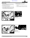
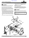
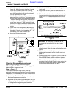
Checking Driveline Minimum Length
Refer to Figure 1-1 on page 8:
1. Start tractor and slowly engage tractor’s hydraulic
3-point to lift the lower arms until the Rotary Tiller’s
driveline shaft is approximately level with tractor's
PTO shaft.
2. Slide the slip clutch or shear bolt yoke end of driveline
(#12) over the splined input shaft of gearbox (#1).
Secure with driveline yoke locking device.
3. Slide the opposite driveline yoke end over the tractor’s
splined driveline shaft. Secure with driveline yoke
locking device. Skip to step 4 if driveline fits between
tractor and implement.
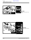
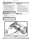
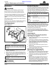
Refer to Figure 1-6 on page 11:
4. The driveline will require shortening if it is too long to
fit between the tractor and tiller gearbox. Shorten
driveline as follows:
a. Raise 3-point lower arms until tiller and tractor
PTO shafts are approximately level with each
other. Securely block Rotary Tiller frame in this
position. Set tractor in park, shut tractor engine
off, set park brake and remove switch key.
IMPORTANT: Always check driveline maximum and
minimum length during initial setup, when connecting
to a different tractor and when alternating between
using a quick hitch and a standard 3-point hitch. More
than one driveline may be required to fit all
applications.
IMPORTANT: Itis necessary to aligning the tractor’s
PTO shaft level with tiller’s PTO shaft when checking
to see if the driveline’s minimum length is correct.
Too long a driveline can damage the tractor, gearbox
and driveline.
IMPORTANT: For easier access to gearbox input
shaft, remove driveline guard (#10).
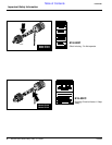
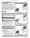
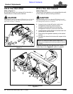
Figure 1-3
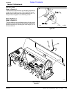
Figure 1-4
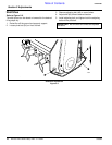
Figure 1-5
Implement End
Tractor End
Push Pin Coupling
Push Pin Coupling
With
Shear Bolt Protection
22232
Implement End
Tractor End
Pull Collar Coupling
Push Pin Coupling
With
Shear Bolt Protection
22233
Implement End
Tractor End
Push Pin
Coupling
Pull Collar Coupling
With
Slip Clutch Protec-
22234