


4
Manual No. 701-149M 06/21/07
Land Pride
Assembly Instructions
■
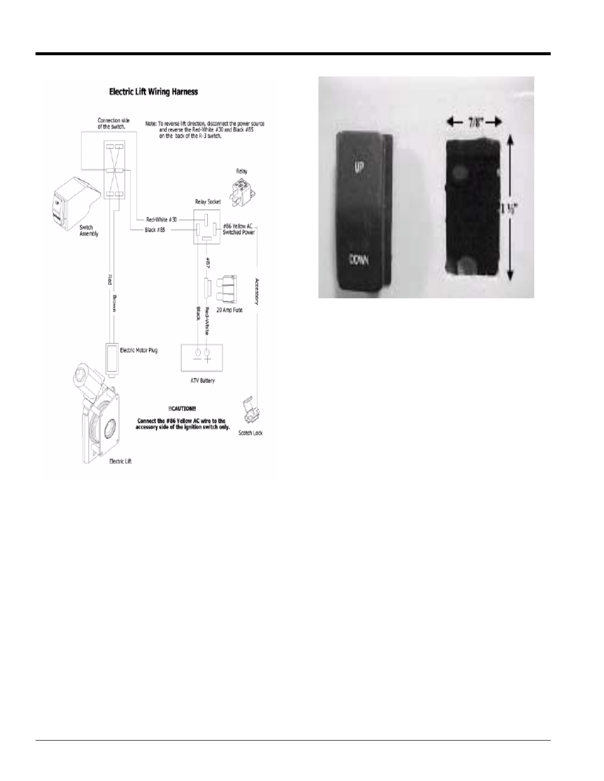
Switch Installations
Choose a place for the switch assembly that is free
from obstructions and does not interfere with the
normal functions of the machine.
Method One:
Place the 13/16 Vinyl Coated Cable Clamp (#16) around
machine’s front rack and secure using one 10-3/4" Pan
head Bolt (#19), #10 Star Washer (#17), 5mm Flat
Washer (#18), 10-24 Nylock Nut.
Method Two:
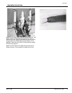
This method you will not use the Switch Housing (#14).
Locate a convenient place on the dash to mount the
switch. Cut a rectangular hole 7/8" x 1 ". Press the switch
into the rectangular hole. See picture below.
Route the Red and Black wires to the battery.
These wires must be well clear of any moving parts on
the machine
Do not allow the wires to come in contact with any hot
parts of the machine, such as the exhaust or cylinder
head.
Secure the ring terminal on the black wire to the battery
negative post.
Install the ring terminal on the red-white wire to the
positive battery terminal.
Route the red and brown leads of the Wiring Harness
(#27) to the front of the machine and connect to the lift
motor plug.
These wires must bewell clear of any moving partsof the
machine
Do not allow the wires to come in contact with any hot
parts on the m achine such as the exhaust or cylinder
head
Allow plenty of slack for vertical movement of the plow
between the tie point on the machine and the electric lift
motor.
Plug the Relay (#13) into the relay socket on the Wiring
Harness (#12).
With a 12-volt test light or meter locate a wire that is only
hot when the ignition switch is in the "on" position.
Use the blue scotch lock (#22) tap connector to connect
the yellow wire from the electronic module to this wire.
Note: Failure to connect the yellow wire to a wire that is
energized only when the ignition switch is in the "on"
position, will discharge the battery.
Check your electrical connections and make sure there