


11
Section 1: Assembly and Set-up
3/21/07
FM3188 & FM4188 Flail Mowers 309-523M
Land Pride
Table of Contents
Driveline Minimum Length
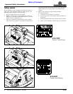
Refer to Figure 1-4:
1. Start tractor and slowly engage 3-point controls to
move lower arms until the gearbox shaft is
approximately level with the tractor's PTO shaft.
2. Slide inner yoke of driveline over the gearbox shaft
and secure with locking collar.
3. Slide outer yoke of driveline over the tractor PTO
shaft and secure with locking collar. Skip to
"Driveline Maximum Allowable Length" if driveline
fits.
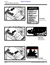
4. The driveline will require shortening if it does not fit
between tractor and mower. Shorten driveline as
follows:
a. Raise or lower 3-point lower arms until mower and
tractor PTO shafts are approximately level with
each other. Securely block Flail Mower frame in
this position.
b. Set tractor in park, shut tractor engine off, set park
brake and remove switch key.
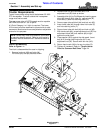
c. Pull driveline apart into two sections as shown in
Figure 1-4. Attach outer driveline universal joint to
the tractor PTO shaft. Attach inner driveline
universal joint to the gearbox shaft. Pull on each
driveline section to be sure universal joints are
secured to the shafts.
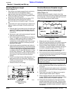
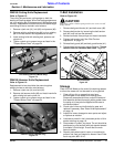
d. Hold driveline sections parallel to each other to
determine if they are too long. The inner and outer
shields on each section should endapproximately
1" short of reaching the universal joint shield on
the adjacent section (see “B” dimension). If they
are too long, measure 1" (“B” dimension) back
from the universal joint shield and make a mark at
this location on the inner and outer driveline
shields.
e. Cut off inner shield at mark (“X” dimension). Cut
same amount off inner shaft (“X1” dimension).
Repeat cut off procedure (“Y”&“Y1” dimensions)
to cut outer driveline half.
f. Remove all burrs and cuttings.
Driveline Shortening
Figure 1-4
22009
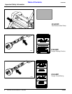
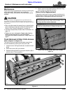
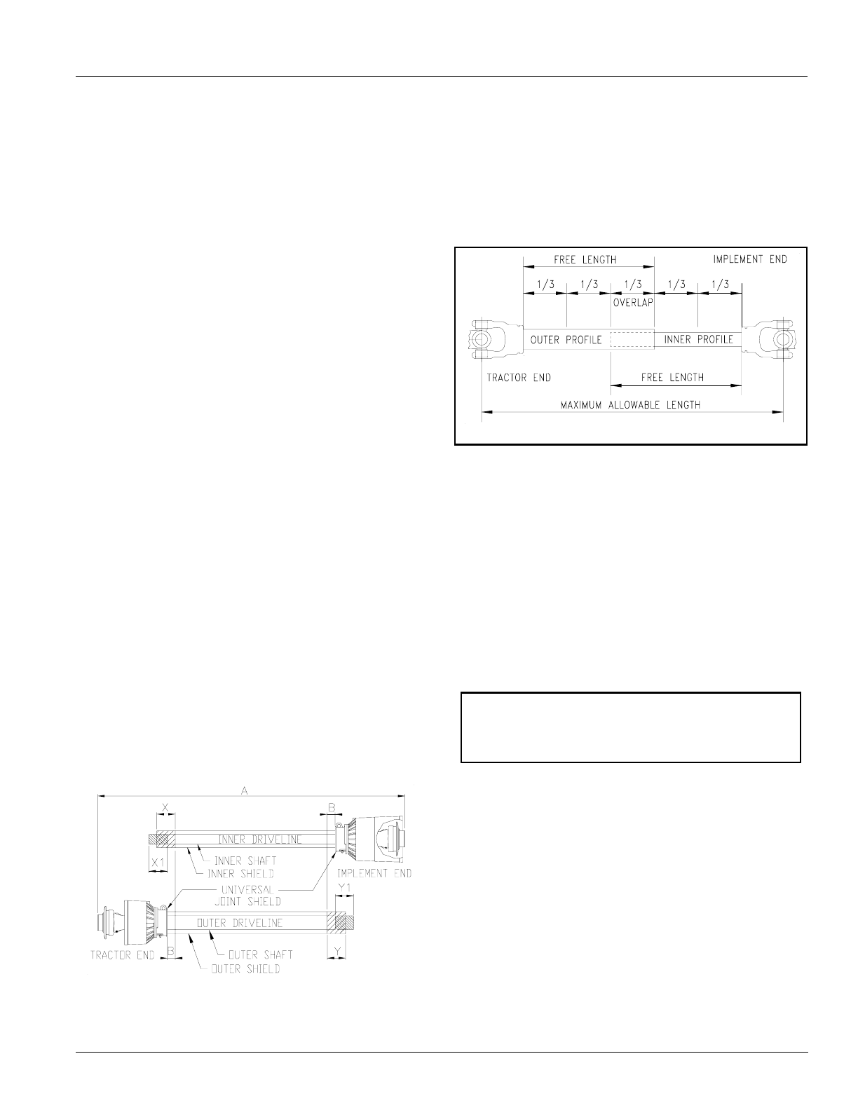
Driveline Maximum Allowable Length
Be sure to check driveline minimum length before
checking driveline maximum allowable length.
Refer to Figure 1-5:
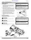
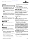
Driveline maximum allowable +length, when fully
extended, must have a minimum overlap of profile tubes
by not less than 1/3 the free length with both inner and
outer profile tubes being of equal length.
Driveline Maximum Length
Figure 1-5
1. Measure and record driveline free length.
2. Apply multi-purpose grease to the inside of the outer
driveline profile and reassemble the two profiles.
3. Move driveline halves together until profile tubes
overlap by 1/3 the free length. Measure and record
maximum allowable length shown in Figure 1-5.
4. Attach inner driveline yoke to gearbox shaft and
outer driveline yoke to tractor's PTO shaft.
5. The driveline should now be moved back and forth to
insure that both ends are secured to the PTO shafts.
Reattach any end that is loose.
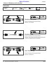
6. Hook one driveline safety chain in the hole on the
outer driveline yoke shield and the opposite end to
the tractor.
7. Hook the second driveline safety chain in the hole on
the inner driveline yoke shield and the opposite end
to the mower.
8. Start tractor and raise Flail Mower just enough to
remove support blocks used in step 4a.
9. Slowly engage tractor’s 3-point controls to lower
mower.Check for sufficient drawbar clearance. Move
drawbar ahead, aside or remove if required.
10. Raise and lower implement to find the maximum
possible extended driveline length. Check to make
certain that the driveline has not extended beyond
the maximum allowable length recorded in step 3 of
this section.
24513
Outer Shielding has been removed for clarity.
IMPORTANT: The two supplied safety chains must
be attached to outer and inner driveline yoke shields
and to the mower deck and tractor to keep driveline
shields from rotating.