


11
Section 2: Operating Instructions
10/11/06
FD2560, FD2572, AT2560 & AT2572 Grooming Mower, 3-spindle 310-148M
Land Pride
Table of Contents
General Description
The operator is responsible for the safe use of this
machine. Read and understand the safety section before
continuing.
This section covers the procedures needed to operate
this machine. Properly read and understand this section
before operating.
Pre-Start Instructions
Tractor Requirements
This mower is designed with a 3-Point category I hitch.
Horse power rating of the tractor should not exceed30 PTO
horse power on 60 inch units and 35 PTO horse power on
72 inch units. PTO Speed of tractor should be 540 RPM.
Tractor Hook-Up
1. Be certain that the tractor draw bar will not interfere.
Move draw bar ahead or remove if required. Draw bar
should also be checked for clearance when unit is
being raised for the first time.
2. Align lower link arms of tractor to hitch lugs on
mower. Insert lower hitch pins into lower ball swivels
and attach lynch pins.
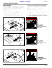
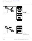
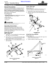
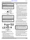
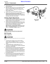
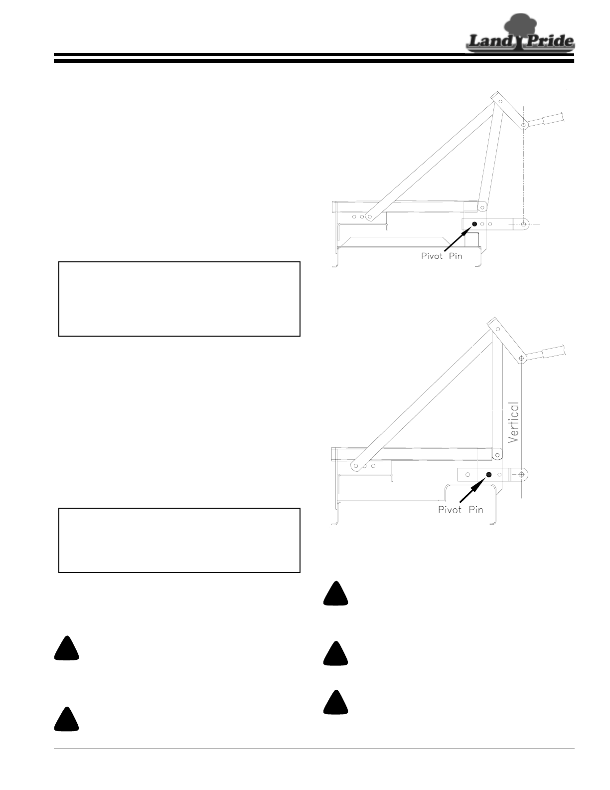
3. Referring to Figure 2-1, attach tractor top link to
upper floating hitch on mower with pin supplied.
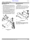
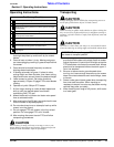
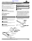
4. Adjust the tractor top link in or out to place the upper
hitch pin vertically above the lower hitch pins as
shown in Figure 2-2, to allow mower flotation.
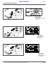
Driveline Installation
An additional driveline may be required if the mower is to
be used on more than one tractor especially if a quick
hitch is used.
!
CAUTION
Do not use a PTO adaptor with a quick hitch. A PTO adapter
will increase strain on the tractor’s PTO shaft resulting in
possible damage the shaft and driveline.
!
WARNING
Damaged drivelines can cause serious injury or death.
NOTE: In order to maintain steering control, ballast
may have to be added to your tractor. To determine
whether or not to add ballast, refer to your tractor
operator’s manual for weight requirements and to the
“Specifications and Capacities” chart for the weight
of the unit.
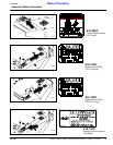
NOTE: The initial position of the Upper Hitch Arms
and the Lower Hitch Lugs should be in the back
position. If there is a clearance problem refer to the
“Adjustment Section” under “Floating & Front To
Back Hitch Adjustments” page 14.
Front Position Hitch Adjustment
Figure 2-1
Back Position Floating Hitch Adjustment
Figure 2-2
!
CAUTION
Tractor PTO shield and all Grooming Mower guards must be
in place at all times during operation!
!
WARNING
Damaged drivelines can cause serious injury or death.
!
CAUTION
Always engage parking brake, shut off tractor and remove key
before dismounting from tractor.
11915
Section 2: Operating Instructions