


10
Section 1: Assembly & Set-up
FD2560, FD2572, AT2560 & AT2572 Grooming Mower, 3-spindle 310-148M
10/11/06
Land Pride
Table of Contents
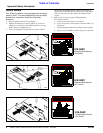
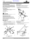
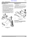
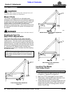
Gauge Wheel Assembly
Refer to Figure 1-5:
1. The rear gauge wheel arms (#1) are bolted to the
frame backwards from factory. Remove the 3/8" x 3"
long bolt (#2), hardware and gauge wheel arm (#1).
2. Bolt the rear gauge wheel arms (#1) to the mounting
channels on the mower frame using 3/8" x 3" long
bolt (#2) and hardware shown.
3. Insert the 1" diameter shaft of the gauge wheel yoke
(#3) into the bushings on the gauge wheel arm (#1),
noting the amount of spacers (#4) added to top or
bottom depending on cutting height {refer to Section
3“Cutting Height Adjustments” on Page 15}.
4. Secure shaft to wheel arm with 1/4" lock pin (#5). Be
sure all the spacers are arranged the same on each
wheel assembly. Tighten all hardware to values
listed in the “Torque Values Chart” in the appendix.
Gauge Wheel Assembly
Figure 1-5
13577
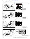
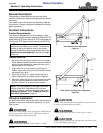
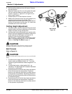
Grass Chute Assembly
Refer to Figure 1-5:
1. Loosen upper pivot bolt (#1) and remove lower
thumb screw (#2).
Hinge chute down and install thumb screw (#2) and flat
washer(#3). When set at position desired, tighten down
upper pivot bolt (#1) and lock nut (#4). Do not tighten
completely. Allow chute to hinge. Lock down lower
thumb screw (#2) with flat washer (#3).
2.
Grass Chute Assembly
Figure 1-6
Final Inspection
After completing the “Dealer Assembly and Setup”
section, fill out the “Warranty Registration Form &
Inspection Report” in this manual.
13544