12
Section 1: Assembly and Set-Up
BH3512 Backhoes 340-131M
7/14/08
Land Pride
Table of Contents
boom, the power crowd side of the dipper stick, and both
sides of the swing. If the circuit relief is faulty, it could be
caused by dirt. This could be rectified by removing and
cleaning the circuit relief. See instructions for Circuit
Relief Valve.
Checking the Cylinders
Take a reading at idle speed, with cylinder at end of
stoke. Next take another reading at high speed. If the
pressure increases with speed, it would indicate a faulty
cylinder.
Return Hose:
If the return hose bursts, check to see if the high-
pressure line is connected to pressure port of the
backhoe, or if the return hose is restricted (usually by an
oil coupler).
Testing Closed Center System
On a closed center system the gauge will read the same
as the tractor’s system pressure rating. (e.i. older Closed
Center John Deere’s will read 2200 to 2250 PSI)
Checking a Single Circuit
If there is a loss of power on one circuit, it may be
checked by actuating the valve. The pressure should
drop until the end of cylinder stroke, if the pressure does
not return to the original reading, this would indicate a
faulty cylinder or circuit relief. Circuit reliefs are on the
down stroke of the boom, the power crowd side of the
dipper stick, and both sides of the swing. If the circuit
relief is faulty, it could be caused by dirt. This could be
rectified by removing and cleaning the circuit relief.
Checking the Pump
If the tractor’s PSI is rated at 2250 lbs, and the gauge
reads less, the tractor’s hydraulic system is faulty or the
backhoe’s valve is improperly set for closed center
operation. See Closed Center Hydraulic System Section.
Checking The Cylinders
Take a pressure reading at idle speed, with cylinder at
end of stoke. Next take another pressure reading at high
speed. If the pressure increases with speed it would
indicate a faulty cylinder.
For other hydraulic problems refer to Troubleshooting
Section.
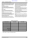
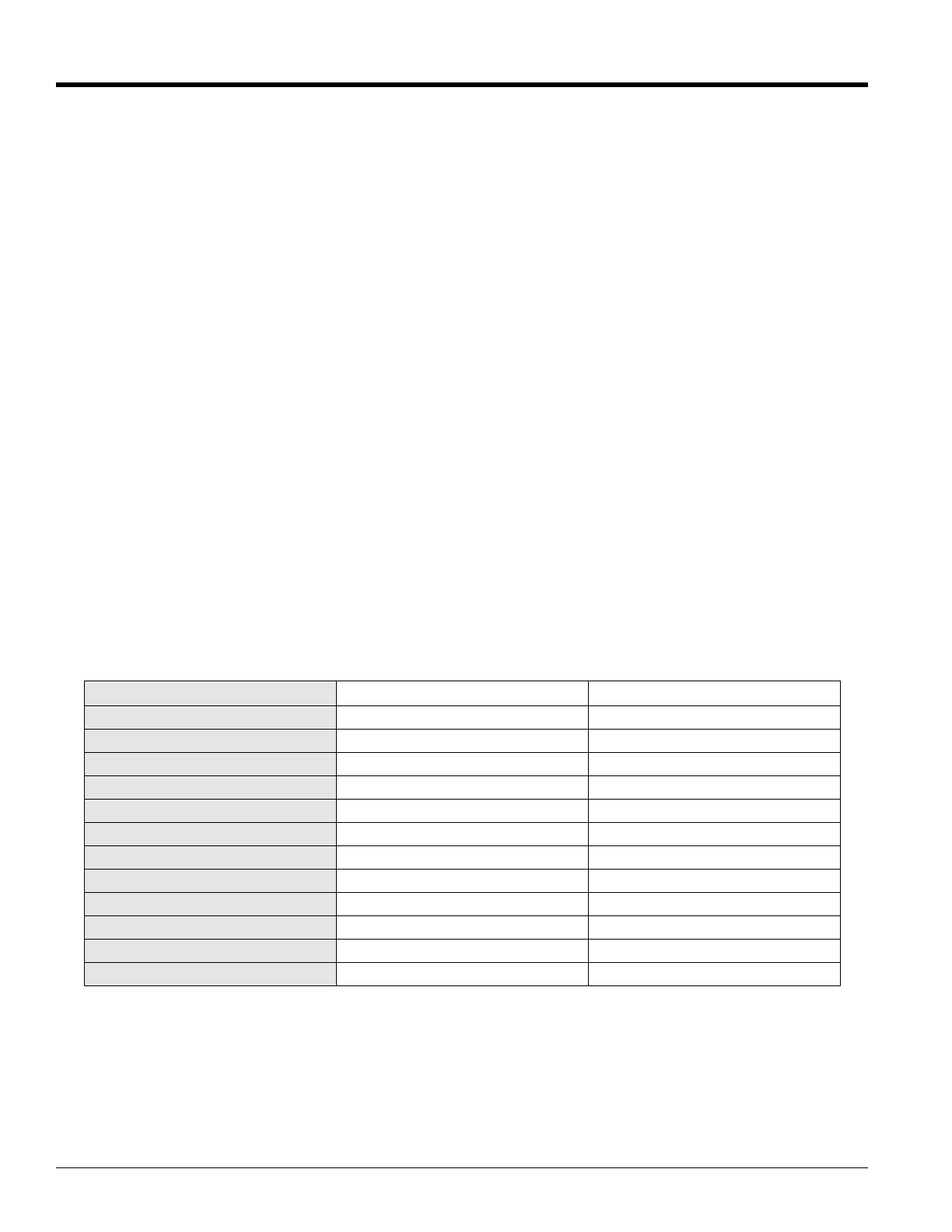
Before calling your dealer, fill in the Hydraulic Testing
Chart below. The chart below will enable the service man
to diagnose nearly all-hydraulic problems you may be
having with your backhoe. Be certain that the cylinder is
at the end of the stroke when the readings are taken.
Hydraulic Testing Chart
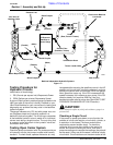
* Reder to Figure 1-5 on Page 13 for Cylinder Locations.
Cylinder Function* PSI Idle Speed PSI Full Speed
Stabilizer - Up R.H.
Stabilizer - Down R.H.
Stabilizer - Up L.H.
Stabilizer - Down R.H.
Dipper Stick - In
Dipper Stick - Out
Swing - Left
Swing - Right
Bucket - Open
Bucket - Closed
Boom - Up
Boom - Down


