11
Section 1: Assembly and Set-Up
7/14/08
BH3512 Backhoes 340-131M
Land Pride
Table of Contents
Testing Procedure for
Hydraulic Circuits
Identification of terminology:
1. PSI (Pounds per square inch)-Represents Power
2. GPM (Gallons per minute)-Represents Speed
A glycerin filled hydraulic pressure gauge (located on the
right hand side of the valve) is factory installed on your
Land Pride Backhoe for your convenience in testing and
diagnosing any problem that may arise in the backhoe
hydraulic system.
The gauge indicates only PSI, but with proper use, one
can diagnose almost any hydraulic problem in a
backhoe’s hydraulic system. The first thing to remember
is the backhoe hydraulic valve is made of six individual
valves, each doing a single function. The only thing that
is common to the valve bank is the hydraulic valve and
the master relief valve.
Testing Open Center System
Check the pump and master relief: If a problem exists on
all hydraulic circuits, the pump or master relief usually
causes it. To check these, operate the tractor at a very
low speed while actuating the stabilizer control in the UP
position until the cylinder is entirely collapsed, continue
holding the control lever and read the PSI on the gauge.
Next, speed the tractor up. If the PSI increases as the
speed increases, this indicates a worn pump. If the PSI
remains steady, but less than 2250 lbs, then the
backhoe’s master relief is set too low (See HOW TO SET
PRESSURE ON MAIN RELIEF VALVE section).
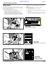
!
CAUTION!
Never attempt to adjust any relief valve without a gauge in a
pressure line.
Checking a Single Circuit
If the power or speed goes down on one function the
problem is in that valve section, circuit relief, cylinder, or
a restriction in the hoses (The boom and stick are
restricted to prevent sudden drop). To check the
individual circuit, move the cylinder to the end of its
stroke, and continue holding the valve, then take a
pressure reading and compare the readings, they should
be the same. If they are not the same it could be a faulty
circuit relief. Circuit reliefs are on the down stroke of the
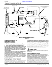
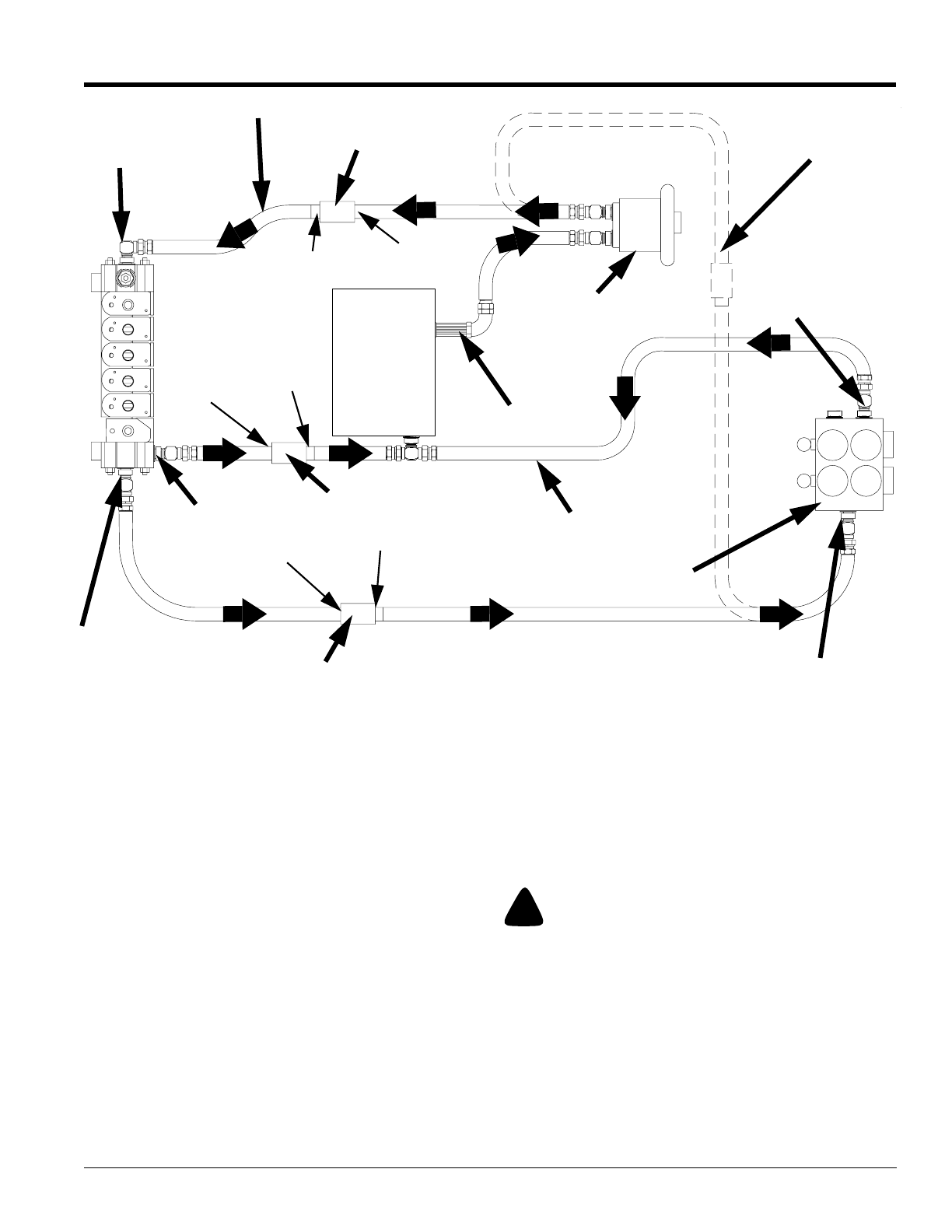
Backhoe Independent Hydraulic Systems
Figure 1-4
19548
Pump
(Rear, Front or Tractor)
Suction Filter
(Backhoe, Tractor)
Oil Reservoir
(Backhoe or
Tractor Sump)
Inlet Valve of
Backhoe Valve
Power Beyond Port
Tank
Press.
Return Outlet
Valve Return Hose
Tractor Loader Valve
Inlet of Valve
(Male)
(Female)
Quick Coupler
Quick Coupler
(Male)
(Female)
Return Port
Pressure Line
(Female)
(Male)
Quick Coupler
Circuit when Backhoe
is removed


