


9
10/13/08
RTA10 & RTA15 Series Rotary Tillers 311-252M
Land Pride
Section 1 Assembly and Set-Up
Table of Contents
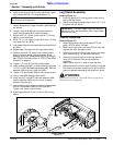
Leg Stand Assembly
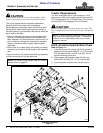
Refer to Figure 1-1:
1. Insert leg stand (#13) into leg stand holder on the
end of the tiller frame.
2. Adjust to the desired height and pin with 1/4” x 1 3/4”
long wire lock pin (#14).
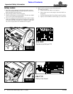
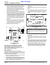
Tractor Hook-Up
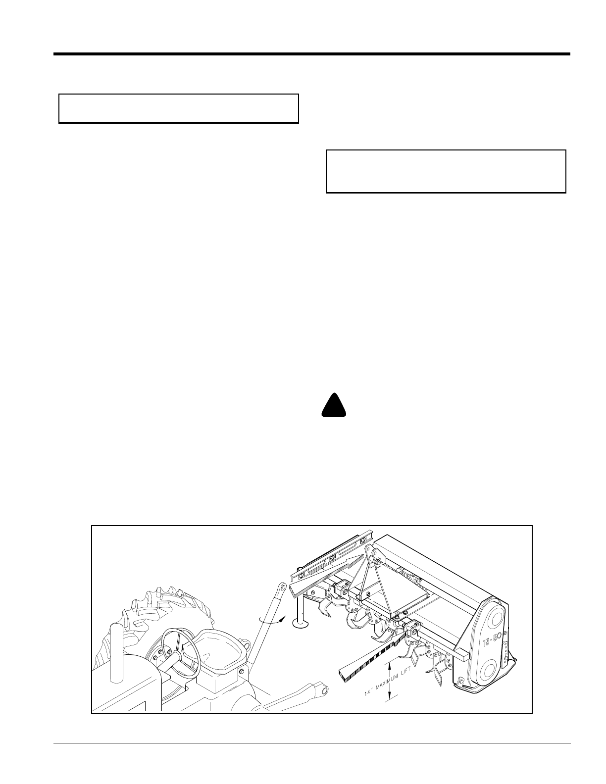
Refer to Figure 1-2:
1. When using tractors with multi-speed PTO, be
certain PTO is set for 540 rpm.
2. Back tractor up to tiller until lower 3-Point links are
aligned with hitch clevises on tiller.
3. Secure the tractor’s 3-Point lower links to the lower
hitch clevises using 7/8" diameter hitch pins.
4. Secure the tractor’s top link to the tiller top hitch
using a 3/4" diameter hitch pin (supplied by
customer).
Adjust tractor top link in order to level the tiller.
5. Adjust the tractor’s 3-Point hitch lift height so that the
tiller tines are not lifted more than 14 inches off the
ground to prevent damage to the driveline u-joints.
!
WARNING
Lifting unit more than 14” high while PTO is engaged may
damage driveline components.
IMPORTANT: The three upper holes are used for
parking the tiller and the bottom hole is used when
the tiller is in use.
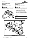
Tractor Hook-Up
Figure 1-2
22191
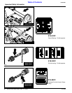
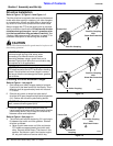
4. Install driveline guard (#10) to the top of the 3-point
hitch plates with four 1/4” wing screws (#11).
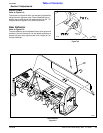
5. Mount left hand clevis (#15) over square tube as
shown. Make certain longer chamfer is positioned on
the bottom.
6. Locate u-bolt (#16) behind the square tube and
insert through clevis (#15) holes as shown.
7. Secure with 1/2”-13 hex nylock nuts (#17). Do not
tighten nuts at this time.
8. Drive 1/4” x 1 3/4” rollpin into pin (#19) into 1/4” hole
into lower hitch pin (#18).
9. Insert lower hitch pin into clevis and secure with linch
pin (#20).
10. Repeat step 5 through 9 for the right hand clevis.
11. Position clevis 26 7/8” apart from inside of clevis
plate to inside of clevis plate and center off the
gearbox input shaft. When offsetting tiller to the right,
see “RTA10 Tiller Hitch Offset” or “RTA15 Tiller Hitch
Sideshift” on page 14.
12. Tighten 1/2” nuts (#17) to the correct torque.
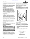
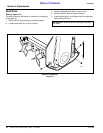
13. Install manual tube (#21) to hitch plate (#7) with two
1/4”-20 x 1 GR5 hex head cap screws (#22), SAE flat
washers (#23) and hex nylock nut (#24).
14. Tighten 1/4” cap screws (#22) to the correct torque.
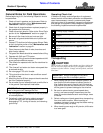
15. Insert u-bolt (#26) through chain (#25).
16. Install two 3/8” nuts (#27), two lock washers (#28)
and flat washers (#29) onto the u-bolt an equal
distance from the end.
17. Insert u-bolt through deflector shield and secure with
tow 3/8” flat washers (#29) and hex nuts (#27).
Tighten nuts to the correct torque.
18. Attach opposite end of chain to slot in tiller frame
above.
NOTE: Remove driveline guard for easier access to
the driveline at the gearbox.