


2
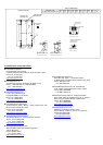
Table 1. Recommended Tilt Angles for Stand Alone
Fixed Systems - Based on Winter Performance
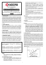
For grid tie installations where the solar modules are attached to a
permanent structure, PV modules should be tilted at an angle equal to
the site's latitude. This will typically result in the highest annual energy
output.
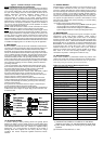
7. INSTALLING KD SERIES MODULES
The minimum spacing of 50mm (2”) is required between PV module
and the mounting surface around the perimeter of PV module. The
frame of each PV module has 9mm (0.35”) diameter mounting holes
(Refer to Module Mounting Specifications). These are used for fixing
PV modules to the supporting structure. PV module frames must be
attached to a support structure using M8 (5/16”) stainless steel screw in
a minimum of four (4) places symmetrical on PV module. The stainless
steel screw used for fixing the module frame should secure with an
adequate torque. (usually, 19 N-m (14 ft-lb).) An example of a ground
mounted structure is shown in Figure 2. The four holes close to the
corners of the module are most often used for installation. Refer to the
Mounting Specifications for the position of these holes. Clearance
between PV module frame and the mounting surface may be required
to prevent the junction box from touching the surface, and to circulate
cooling air around the back of PV module. Spacing between PV
modules must be a minimum of 1/8" (3.2 mm) to allow for thermal
expansion. If the modules are to be installed on the roof or wall of a
building, the stand-off method or the rack method is recommended.
STAND-OFF METHOD: PV modules are supported parallel to the
surface of the building wall or roof. Clearance between PV module
frames and surface of the wall or roof is required to prevent PV module
and / or wiring from damage.
The recommended stand-off height is 4.5” (about 115 mm). If other
mounting means are employed, this may affect the Listing For Fire
Class Ratings.
RACK METHOD: The supporting frame is used to mount PV modules
at correct tilt angles. PV modules specified in this installation manual
are not designed for Building Integrated Photovoltaic (B.I.P.V)
application as part of a roof or wall. The mounting design may have an
impact on the fire resistance.
OTHER: Other method(s) certified by a registered professional
engineer, and in compliance with local codes.
MOUNTING HOLE
ARRAY FRAME
MODULE
FOOT ANGLE
SUPPORT
LEGS
Figure 2. Basic Rack or Stand-off Mounting Structure
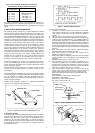
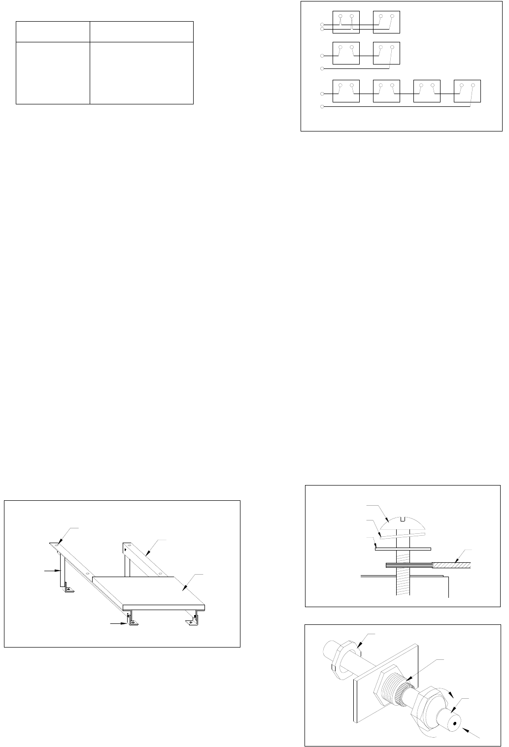
8. MODULE WIRING
As shown in Figure 3 Standard Wiring Examples, Kyocera PV modules
utilize the Type "IM" junction box (see J-box details). This junction box,
located on the back side of the module, is weatherproof and is
designed to be used with standard wiring or conduit connections.
A cable clamp with a minimum rating of IP65 must be used to maintain
the weatherproof integrity of the junction box. Bypass diodes are
preinstalled at factory.
EXAMPLE OF 'IM' TYPE J-BOX WIRING
+
-
24 VOLT (2 SERIES)
+
-
+
+- - + +- -
+
-
12 VOLT (2 PARALLEL)
- ++-
RED
BLACK
21
+--+
1 2
12
BLACK
RED
1
2
RED
12 212121
BLACK BLACK BLACK
48 VOLT (4 SERIES)
Figure 3. Standard Wiring Examples
To wire Kyocera PV modules:
A. Determine the nominal system array voltage of your system.
Each panel is equivalent to a 12 VDC nominal block. Standard
array voltages 12, 24 and 48 volt are shown as examples in
Figure 3.
B. Open the "IM" box cover by loosening the screws in the cover.
C. The wire used to interconnect PV modules may be single or two
conductors, from 14AWG (2.08 mm
2
) up to 10AWG (5.26 mm
2
)
gauge stranded copper wire, in a “SUNLIGHT RESISTANT” and
insulated for 90℃ minimum jacket cable. This cable is suitable for
applications where wiring is exposed to the direct rays of the sun.
The maximum and minimum outer diameters of the cable that may
be used with the cable connector are 8 mm and 6 mm respectively
(Figure 4).
D. Using a flat blade screw driver, remove only the appropriate
"KNOCK-OUTS" from the sides of the "IM" box.
E. Route wires through the knock-outs and clamps refer to
installation example (see Figure 5).
F. Gently hand tighten the terminal screws with cross slot (Phillips
-head) screwdriver. Do not over tighten, as the terminal can be
damaged.
(Recommendation Torque : 1.5N-m (13.3 in-lb)
G. The output wiring from the final module is generally run to a
separate array junction box. In commercial system, this wiring
from the array box to the next component (i.e. fuse box. or charge
regulator, etc.) is generally run in conduit. The maximum electrical
rating of an acceptable series fuse is 15 amperes.
H. After checking that PV module wiring is correct, close all the
junction boxes. Use a Phillips head screw driver to secure all
screws on the junction box cover to ensure a waterproof seal.
I. Refer to the cable clamp specifications for KD135SX-UPU and
KD140SX-UPU.
Refer to below for a cable clamp of our designation.
(Manufacturer / Part Number)
Cable Gland : LAPP / S2212 (NPT-1/2")
Nut : LAPP / 911371K (NPT-1/2")
TERMINAL SCREW
SPRING WASHER
CABLE
SQUARE WASHER
Figure 4. Ring or Spade Terminal Connectors
CABLE
NUT
CABLE CLAMP
SITE LATITUDE
IN DEGREES
FIXED TILT ANGLE
0°TO 15
15°TO 25°
25°TO 30°
30°TO 35°
35°TO 40°
40°+
15°
SAME AS LATITUDE
LATITUDE + 5°
LATITUDE + 10°
LATITUDE + 15°
LATITUDE + 20°