


11 GB/IE/CY
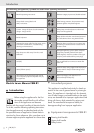
J Check before use that the cutting edge is not
blunt and that its mounting is not damaged. Re-
place blunt or damaged cutting tools in a com-
plete set so as not to create a dynamic
unbalance.
J Check the grass box
10
regularly for signs of
wear or deformation.
J Regularly check all nuts and screws for their
tightness, to ensure a faultless operating condi-
tion for the appliance.
J Avoid all collisions between the appliance and
foreign objects (e.g. branches, stones, metal
parts and toys)! Check the grassed area over
and remove all foreign objects!
J Adjust the cutting height of the appliance such
that thecurved blade bar
21
cannot make con-
tact with the ground (unevenness)!
J In the event of a collision with a foreign object
or unusual vibrations, check the appliance for
possible damage and, if need be, arrange for
it to be repaired.
J Never use the appliance with damaged protec-
tive fittings or coverings or deficient protective
equipments such as deflective or grass box
components.
J For collecting the clippings, use the grass box
exclusively
10
!
J Only exchange damaged or worn parts for
original spare parts!
J Only use replacement cutting tools of the same
type as those fitted into the appliance.
J Switch the lawn mower off and remove the
plug when you transport it, cross areas other
than grass or bring the appliance from or to an
area to be mown.
Q
Commissioning
Q
Assembly
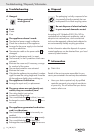
c Danger!
J Carry out the assembly ONLY with the appliance
switched off and separated from the power supply!
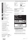
J Avoid causing damage to the power cable
6
e.g. through squashing it!
Tip!
Lift the appliance from its packaging together
with a second person.
Fasten the steering shaft to the appliance.
j Attach the power cable strain relief
7
to the
lower shaft
9
.
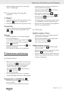
j Place a retaining screw cover
17
on to each of
the tube ends of the lower shaft handle
9
,
see Fig. A.
j Insert the tube ends of the lower shaft
9
into
the two holes in the housing
14
(see Fig. A).
j Screw them down tightly with the two retaining
screws
15
.
j Now push the the retaining screw covers
17
over each of the retaining screws.
j Fasten the upper shaft
2
with the help of both
connecting screws
8
to the lower shaft
9
.
j
Secure the power cable
6
with both cable clips
20
to the upper
2
and lower shafts
9
(see
Fig. C).
Assembling the
10
grass box
j Exactly fit the 2 grass box lower components
together with the grass box upper component.
Begin with the lower components.
The fasteners snap in clearly.
Q
Grass box - fitting / removing
c Danger!
J Switch the appliance off! Wait until the curved
blade bar
21
comes to a complete stop!
Fitting
j Raise up the impact protection flap
11
.
j Attach the grass box
10
to the upper attach-
ment devices
18
and fit it into the clippings
ejection shaft
19
(see Fig. B).
j Lay the impact protection flap
11
onto the
grass box
10
.
General safety advice /Commissioning