


TP-6804 1/15 57Section 4 DC2 Controller Operation
4.2.3 LCD Display
The controller is equipped with a two-line x 16 character
backlit digital display with adjustable contrast. When
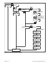
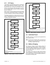
the generator set is running, the messages shown in
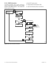
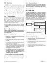
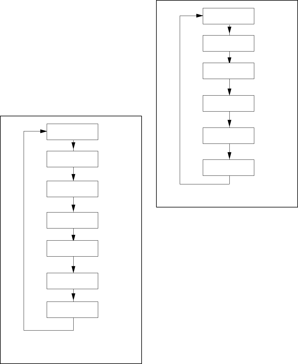
Figure 4-5 are displayed. When the system is in AUTO,
the LCD display steps through the status messages
shown in Figure 4-6.
When a fault or warning condition exists, the controller
will show the corresponding message. See Section 2.5
for more information on fault and warning messages.
The display backlight turns off after abouta minute of no
activity. The backlight turnson whena button ispressed
or when the generator set starts.
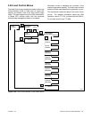
Running
ATS: Normal *
Voltage: 240V
Freq: 60.0Hz
Engine: 72F
Oil Pressure: OK
Battery 12.1V
Runtime: 24.5 h
Next Exercise:
5d 6h 42m
Sample data shown.
Active Alert
(if any)
OnCue Status:
Disconnected [
* Model RXT ATS required
[ OnCue status i s displayed only i f OnCue password has
been reset.
Figure 4-5 Status Displays, Generator Running
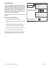
Genset State
Standby
Battery 12.1V
Runtime: 24.5 h
Next Exercise:
5d 6h 42m
Sample data shown.
Active Alert
(if any)
Next Maint:
150h or 12months
OnCue Status:
Disconnected
[ OnCue status i s displayed only i f OnCue password has
been reset.
Figure 4-6 Status Displays, Generator in Standby
4.3 Controller Power
The DC2 controller is powered by the generator set
engine starting battery.
Note: To disconnect controller power, disconnect the
utility power to the generator set and disconnect
the battery (negative lead first).
4.4 Battery Charging
The c ontroller includes a built-in battery charger to
maintain the enginestarting battery. The DC2 controller
monitors the battery voltage and provides a constant
14 ±2% VDC voltage and maximum 2.5 amps to
charge the battery.
The installer must c onnect AC utility power provided
from the building on a breaker-protected circuit for the
built-in battery charger. See the Installation Manual for
instructions to connect power.