


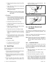

TP-6331 5/04 15Section 3 Scheduled Maintenance
Battery short circuits. Explosion can cause severe injury
or death. Short circuits can cause bodily injury and/or
equipment damage. Disconnect the battery before generator
set installation or maintenance. Remove all jewelry before
servicing the equipment. Use tools with insulated handles.
Remove the negative (--) lead first when disconnecting the
battery. Reconnect the negative (--) lead last when
reconnecting the battery. Never connect the negative (--)
battery cable to the positive (+) connection terminal of the
starter solenoid. Do not test the battery condition by shorting
the terminals together.
Refer to this section for general battery information and
maintenance. Also consult the battery manufacturer’s
instructions for battery maintenance.
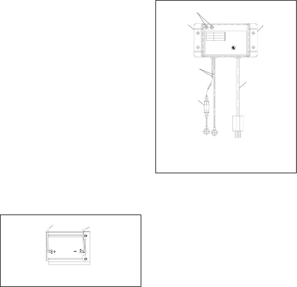
All generator set models use a negative ground with
a12-volt engine electrical system. Consult the
generator set nameplate for the engine electrical
system voltage. Consult the generator spec sheet for
battery capacity recommendations for replacement
purposes. Wiring diagrams provide battery connection
information. See Figure 3-6 for typical battery
connections.
Clean the battery and cables and tighten battery
terminals using the service schedule recommendations.
To prevent corrosion, maintain tight, dry electrical
connections at the battery terminals. To remove
corrosion from battery terminals, disconnect the cables
from the battery and scrub the terminals with a wire
brush. Clean the battery and cables with a solution of
baking soda and water. After cleaning, flush the battery
and cables with clean water and wipe them with a dry,
lint-free cloth.
After reconnecting the battery cables, coat the battery
terminals with petroleum jelly, silicone grease, or other
nonconductive grease.
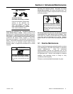
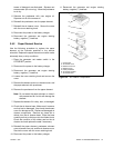
EZ-273000-J
1
2
1. To positive (+) terminal on starter solenoid.
2. To ground (--) terminal on or near starter motor.
Figure 3-6 12-Volt Engine Electrical System Single
Starter Motor, Typical Battery Connection
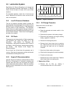
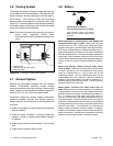
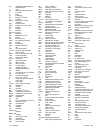
3.9 Battery Charger
The generator set is equipped with a 6-amp
float/equalize battery charger to maintain the engine
starting battery. The charger’s DC leads are factory-
wired. Figure 3-7 illustrates the battery charger.
Periodically tighten all connections. No other
maintenance on the battery charger is required.
INDICATOR
Red:
Red&Green:
Green:
VOLTS=11.8--14.0
AMPS=5.0--6.0
VOLTS=14.0--14.5
AMPS=1.5--5.0
VOLTS=13.0--13.6
AMPS=0.1--1.5
CAUTION:Toreducetheriskofelectricalshock,
connectonlytoproperlygroundedoutlet.
AllowableBatteryTypes:LeadAcida ndGelCell
INPUT:115VAC50/60Hz@1.6A
OUTPUT:12VDC@6Amps
MAX.BAT.:180AmpHr.Max.
DATE:
6AMPAUTOMATIC
BATTERYCHARGER
R
C USLISTED
BATTERYCHARGER
53AB
2608KH
1
1. LED indicators
2. Mounting flanges
3. AC power cord
2
5
2
3
4
4. Fuse
5. Battery leads, 12 VDC
Figure 3-7 6-Amp Float/Equalize Battery Charger