


8
Fig. 4D
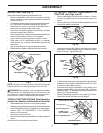
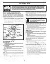
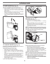
NOTE: The strap hook must go through the discharge chute
only. Do not allow the hook to enter the slot in the tractor
back plate. This will allow the dis charge chute to float with the
mower deck when moving on uneven terrain.
02306
HOOK
BACKPLATE
SLOT
DIS CHARGE
CHUTE
Fig. 5A
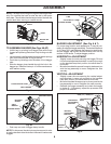
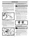
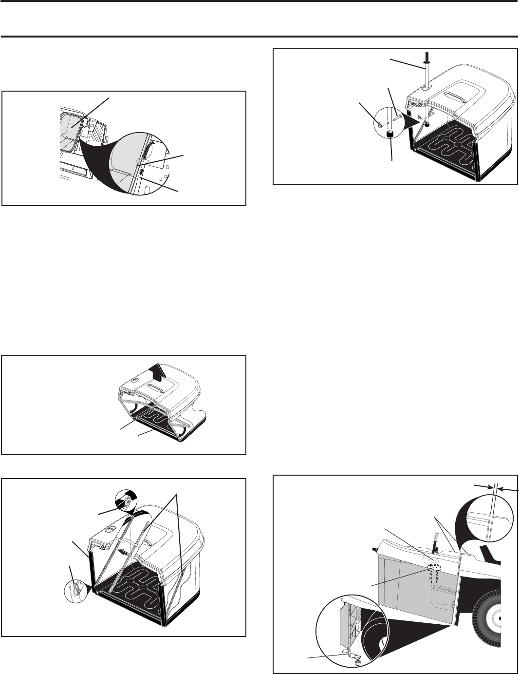
TO ASSEMBLE BAGGER (See Figs. 5A-5C)
• Unfold bag by pivoting front bagger tube all the way
forward and pressing the bottom vinyl binding onto the
tube.
• Inside the bag, install spreader bars and retainer springs
onto pins on both sides of bag as shown.
• Press the vinyl bindings onto the sides of front bagger
tube.
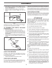
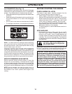
• Slide the bagger dump handle through the hole in the
bagger top, install the clevis pin 10 x 44mm and secure
with retainer spring.
• Push cap over end of bagger dump handle.
NOTE: For future use, the clevis pin may be removed in order
to use the handle to clear the chute in the event it has become
clogged.
Fig. 5C
ASSEMBLY
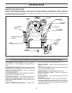
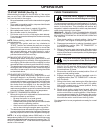
BAGGER ADJUSTMENT (See Fig. 6 & 7)
For proper bag function and appearance, it may be nec-
es sary to adjust the bagger assembly. There should be 6mm
(1/4")-9mm (3/8") gap between the bagger top and fender
and the bagger top surface should be even with the top
surface of the fender. To adjust bagger position:
Fig. 6
HORIZONTAL ADJUSTMENT
• Slightly loosen the nuts securing the bagger RH and
LH hor i zon tal adjustment brackets. Loosen only enough
so the brackets keep their position, but allow them to
be moved.
• Move the brackets the amount forward or back ward you
wish the bag assembly to move. Retighten the nuts
securely.
VERTICAL ADJUSTMENT
• Slightly loosen the nuts securing the vertical adjust-
ment brackets. Loosen only enough so the brackets
keep their position, but allow them to be moved.
• Move the brackets the amount up or down you wish the
bag assembly to move. Retighten the nuts securely.
• Reinstall the bagger as sem bly and check the bagger
to fender fit. If necessary, repeat the procedure until
proper fit is attained.
0
2
9
0
5
VINYL BINDING
FRONT BAGGER TUBE
0
2
9
06
RETAINER SPRING
SPREADER BARS
RETAINER
SPRING
VINYL
BINDING
Fig. 5B
02
9
07
DUMP HANDLE
TUBE
CLEVIS PIN 10 X 44MM
RETAINER SPRING
CAP
Fig. 7
02967
TOP SURFACES
EVEN
6MM (1/4") - 9MM (3/8")
HORIZONTAL
ADJUSTMENT
BRACK ET
VERTICAL
ADJUSTMENT
BRACK ET
BAGGER
LATCH