


7
ASSEMBLY
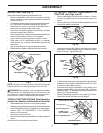
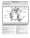
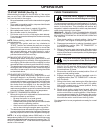
INSTALL SEAT (See Fig. 3)
Adjust seat before tightening adjustment knob.
• Remove adjustment knob and flat washer securing
seat to cardboard packing and set aside for assembly
of seat to tractor.
• Pivot seat upward and remove from the cardboard pack-
ing. Remove the cardboard packing and discard.
• Place seat on seat pan so head of shoulder bolt is
positioned over large slotted hole in pan.
• Push down on seat to engage shoulder bolt in slot and
pull seat towards rear of tractor.
• Pivot seat and pan forward and assemble adjustment
knob and flat washer loosely. Do not tighten.
• Lower seat into operating position and sit on seat.
• Slide seat until a comfortable position is reached
which allows you to press clutch/brake pedal all the
way down.
• Get off seat without moving its ad just ed position.
• Raise seat and tighten adjustment knob securely.
Fig. 3
02
46
6
02464
SEAT PAN
SHOUL DER BOLT
AD JUST MENT KNOB
FLAT
WASH ER
SEAT
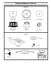
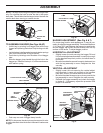
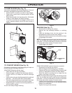
TO INSTALL BAGGER COM PO NENTS TO
TRAC TOR (See Figs. 4A-4D)
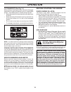
• Remove discharge chute from rear of tractor. Unhook
the two (2) straps and pull chute out and away from
tractor.
• Remove the two (2) 3/8 nuts and flat washers from the
bolts at the tractor back plate.
NOTE: You may now roll your tractor off the skid. Follow the
instructions below to remove the tractor from the skid.
WARNING: Before start ing, read, un der stand and fol low
all in struc tions in the Op er a tion section of this man u al. Be
sure tractor is in a well-ventilated area. Be sure the area in
front of tractor is clear of other peo ple and objects.
TO ROLL TRACTOR OFF SKID (See Op er a tion
section for location and function of con trols)
• Raise attachment lift lever to its highest po si tion.
• Release parking brake by de press ing clutch/brake ped al.
• Place freewheel control in "trans mis sion dis en gaged"
position (See “TO TRANS PORT” in the Op er a tion
section of this manual).
• Roll tractor forward off skid.
• Remove banding holding the deflector shield up against
tractor.
Continue with the instructions that follow.
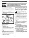
Fig. 4B
• Using the nuts and flat washers removed from tractor
back plate, install the bagger support tube to the back
plate as shown. Tighten securely.
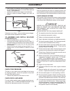
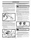
• Install the two upper support brack ets through the back
plate and to the chas sis, install the clevis pin 10x17mm
and secure with retainer spring.
• Assemble both support brackets to the outside of the
bagger support tube using two each 3/8 x 63,5mm
hex bolts13/32" I.D. flat washers and 3/8 locknuts from
parts bag. Tight en securely.
• Replace discharge chute into rear opening of tractor.
Secure the chute with the two hook straps.
02330
SUP PORT
TUBE
FLAT
WASHER
3/8 NUT
BOLT
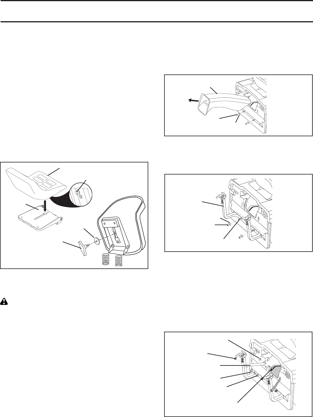
Fig. 4C
02590
CLEVIS PIN 10 X 17MM
3/8 LOCK NUT
SUPPORT BRACKET
10,3MM (13/32")
FLAT WASHER
3/8 X 63,5MM HEX BOLT
RETAINER SPRING
Fig. 4A
02
277
DISCHARGE
CHUTE
3/8 NUT
FLATWASHER