


14 –
English
ASSEMBLY
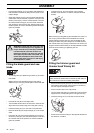
• Fit the support flange (F) on the output shaft. Make sure
that the blade is centered by fitting it to the guide on the
support flange.
• Screw the support cup (E) onto the output shaft threads
(CAUTION! Left-hand thread). Tighten to a torque of 35-
50 Nm (3.5-5.0 kpm). Use the socket spanner in the tool
kit. Note that the locking pin (C) must remain inside the
gear housing to lock the drive disk. Hold the shaft of the
socket spanner as close to the blade guard/combination
guard as possible.
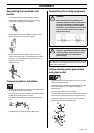
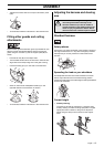
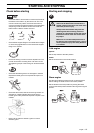
Fitting the blade guard and saw
blade
• The blade guard (A) is fitted using 4 screws (L) as shown.
CAUTION!
Always use the recommended guard for the cutting
attachment you are using. See chapter on Technical data.
• Fit the drive disc (B) on the output shaft.
• Turn the blade shaft until one of the holes in the drive disc
aligns with the corresponding hole in the gear housing.
• Insert the locking pin (C) in the hole to lock the shaft.
• Place the blade (D) and support flange (F) on the output
shaft.
• Fit the nut (G). The nut must be tightened to a torque of
35-50 Nm (3.5-5 kpm). Use the socket spanner in the tool
kit. Hold the shaft of the spanner as close to the blade
guard as possible.
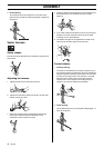
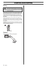
To tighten the nut, turn the spanner in the opposite
direction to the direction of rotation (Caution! left-hand
thread).
When loosening and tightening the saw blade nut, there is a
risk of injury from the teeth of the saw blade. You should
therefore always ensure that your hand is shielded by the
blade guard when doing this. Always use a socket spanner
with a shaft that is long enough to allow this. The arrow in the
diagram shows the area where you should operate the socket
spanner when loosening or tightening the nut.
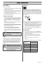
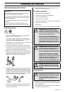
Fitting the trimmer guard and
trimmer head Trimmy SII
• Fit the correct trimmer guard (A) for use with the trimmer
head. Secure the trimmer guard using the 4 screws (L)
and the support plate (M) as shown.
• Fit the drive disc (B) on the output shaft.
• Turn the blade shaft until one of the holes in the drive disc
aligns with the corresponding hole in the gear housing.
• Insert the locking pin (C) in the hole to lock the shaft.
• Screw on the trimmer head (H) in the opposite direction to
the direction of rotation.
!
WARNING! Tighten the lock screw (N) in the
center hole of the support cup. Tighten to a
torque of 35-50 Nm (3.5-5.0 kpm), CAUTION!
Left-hand thread. If the lock screw is not
fitted in the support cup, there is a risk that
the support cup will come unscrewed. This
means that the blade will also come loose,
which could result in serious or fatal injury
to the operator or others.
L
A
CAUTION! If the machine is to be used with a trimmer
head, the fast idle speed must be reduced by 400-500 rpm.
See instructions under the heading Carburettor.
G
F
D
B
C
B
A
L
M
C