


14 – English
ASSEMBLY
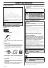
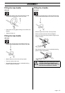
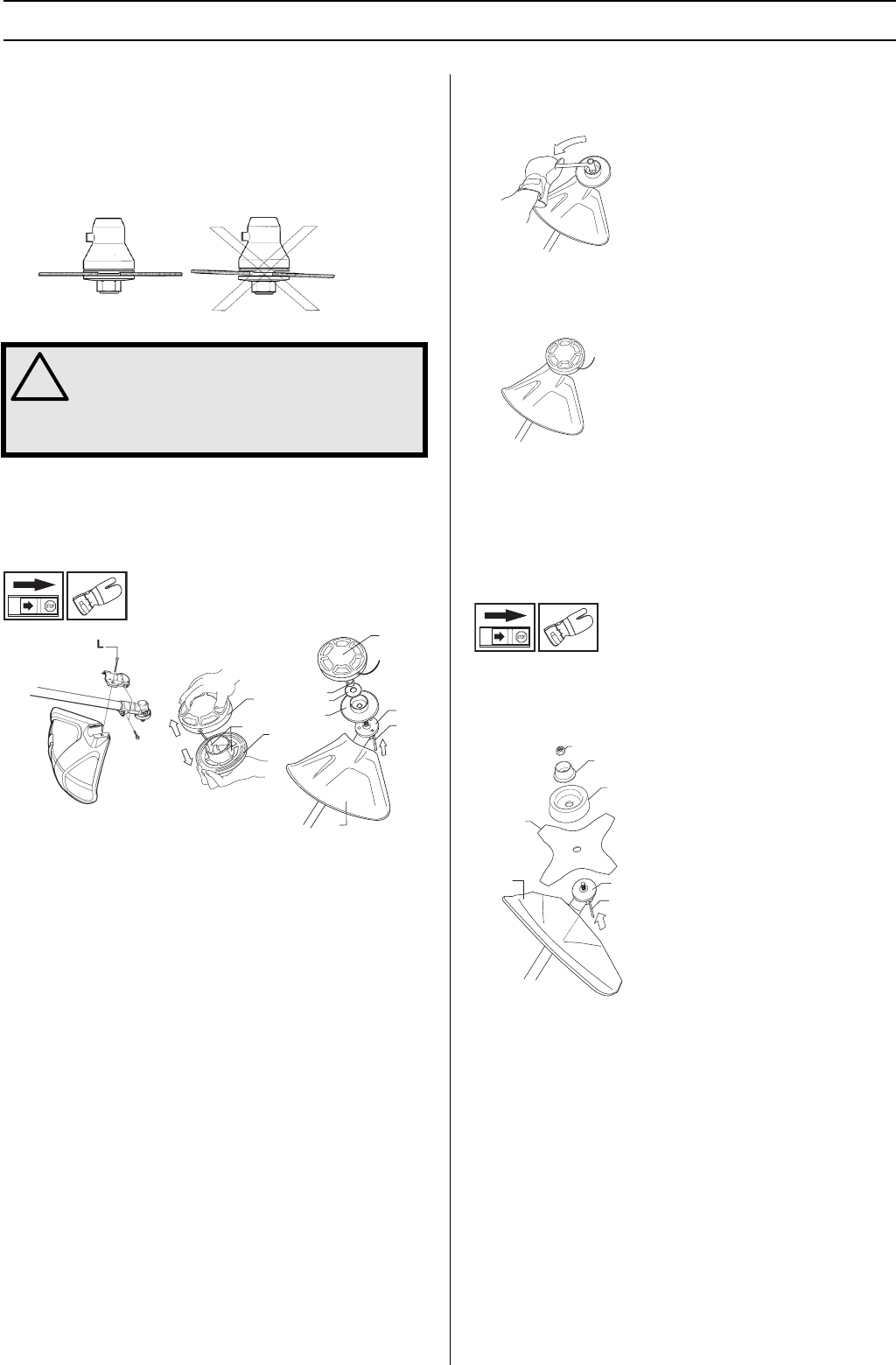
Fitting blades and trimmer heads
When fitting the cutting attachment it is extremely important
that the raised section on the drive disc/support flange
engages correctly in the centre hole of the cutting attachment.
If the cutting attachment is fitted incorrectly it can result in
serious and/or fatal personal injury.
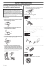
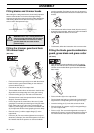
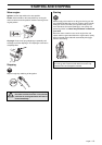
Fitting the trimmer guard and Auto
32 trimmer head
(GC 2125)
• Fit the correct trimmer guard (A) for use with the trimmer
head. Hook the guard onto the fitting on the shaft and
secure it with the bolt (L).
• Fit the drive disc (B) on the output shaft.
• Turn the blade shaft until one of the holes in the drive disc
aligns with the corresponding hole in the gear housing.
• Insert the locking pin (C) in the hole to lock the shaft.
• To fit the trimmer head, first separate the two halves (see
diagram). Proceed as follows:
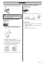
• Insert a finger into the centre hole of the cover (I) while
grasping the cover with your other fingers. Using the index
finger and thumb of your other hand, release the two
catches (J) that engage in the cut-outs in the bottom half
(K). Pull apart the trimmer head, grasping the cover firmly.
• Place the cover (I) and the support flange (F) on the
output shaft.
• Fit the nut (G). The nut must be tightened to a torque of
35-50 Nm (3.5-5 kpm). Use the socket spanner in the tool
kit. Hold the shaft of the spanner as close to the blade
guard as possible. To tighten the nut, turn the spanner in
the opposite direction to the direction of rotation (left-hand
thread).
• Fit the bottom half of the trimmer head (K) to the cover (I)
by pressing them together, with the cut-outs on the bottom
half aligned with the catches on the cover.
• To dismantle, follow the instructions in the reverse order.
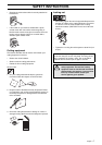
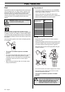
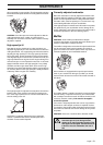
Fitting the blade guard/combination
guard, grass blade and grass cutter
(GC 2125)
• Hook the blade guard/combination guard (A) onto the
fitting on the shaft and secure with the bolt. CAUTION!
Use the recommended blade guard. See the Technical
data section.
• Fit the drive disc (B) on the output shaft.
• Turn the blade shaft until one of the holes in the drive disc
aligns with the corresponding hole in the gear housing.
• Insert the locking pin (C) in the hole to lock the shaft.
• Place the blade (D), support cup (E) and support flange
(F) on the output shaft.
• Fit the nut (G). The nut must be tightened to a torque of
35-50 Nm (3.5-5 kpm). Use the socket spanner in the tool
kit. Hold the shaft of the spanner as close to the blade
!
WARNING! Never use a cutting attachment
without an approved guard. See the chapter
on Technical data. If an incorrect or faulty
guard is fitted this can cause serious
personal injury.
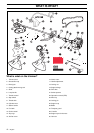
G
F
I
A
B
C
K
J
I
K
G
F
D
B
C
A
E