


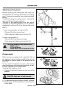
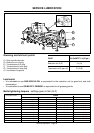
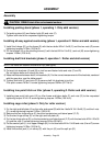


CAUTION: FIRMLY block tiller on horizontal surface.
Installing parking stand (phase 1, operating 1. Only skid version)
1) Put parking stand (A) and fasten bolts (B) and nuts (C).
Tighten lock nuts to the requested tightening torque.
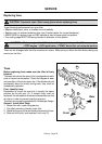
Installing all assy against overturning (phase 1, operation 2. Roller and skid version)
1) Install the linkage (D) on the frame (E) with the two bolts M14x1.5x45 (F) and the two nuts (G) screw
tightening torques 143Nm (105 lib-ft).
2) Fix the bracket (H) on the levelling bonnet (I) with the bolt M14x1.5x45 (L) and nut (M) screw tightening
torques 143Nm (105 lib-ft).
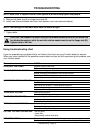
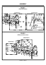
Installing draft link brackets (phase 2, operation 1. Roller and skid version)
NOTE: the holes on bracket should be on up (see figure)
3) Put each link brackets (A) and (B) on tool bar and fasten bolts and nuts (C and D).
Do not tighten bolts and nuts at this time.
4) Measure distance between draft, link brackets (A). For the correct measurement of the brackets, cantered
with the gear box, see the table page 4.
5) Tighten lock bolts (C) and nuts (D) to secure draft link brackets to tool bar.
Fine pitch screws: M18x1.5 screw tightening torques 308Nm (227 lib-ft).
Installing tree point hitch on tiller (phase 2, operating 2. Roller and skid version)
1) Installing tree point hitch point (E) on tiller frame and tigten bolts (F) and nuts (G) to the requested
tightening torque. M14x1.5 screw tightening torques 143Nm (105 lib-ft).
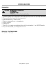
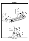
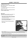
Installing cage roller (phase 3. Only for roller version)
1) Fix the right and left plate (A) on the roller side panel (B) with the 4 bolts M 16x1.5x45 (C) and the 4 nuts
(D), screw tightening torques 214Nm (158 lib-ft).
2) Remove the two hinge stirrup (E) from the transmission and lateral panel (F, G).
3) Put the two hinge stirrup (E) on the right and left plate (A).
4) Fix the two hinge stirrup (E) on the transmission and lateral panel (F, G) with the two bolts M12x1.25x35
(H) and the nuts (I) screw tightening torques 91Nm (68 lib-ft).
5) Put the central jack (L) in to upper linkage (M), fix the tree bolts M14x1.5x35 and nuts (H and O) screw
tightening torques 143Nm (105 lib-ft).
6) Install the central jack (L) on stirrup (P) with the pin (Q) and the split pin (R).
ASSEMBLY
Assembly - Page 23
Assembly