


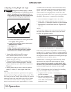
• Adjusting Cutting Height and Angle
Help prevent bodily injury or death
caused by entanglement in rotating driveline or
blades. Entanglement in rotating driveline or
being struck by blades can cause serious injury
or death. Before making any adjustments:
a. Lower machine until rear wheel just touches
or
is
slightly above ground.
b. Engage tractor parking brake and/or place
transmission in “PARK”.
c. Disengage PTO.
d. Shut off tractor engine and remove key.
e. Wait until all moving parts have stopped.
f. Disconnect PTO driveline from tractor.
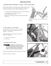
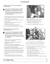
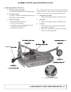
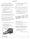
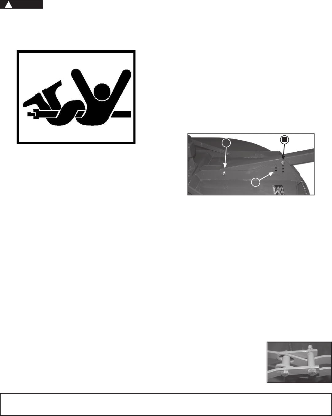
1. Loosen bolt and lock nut (B), remove
bolt, washers and lock nut (A), raise
tailwheel to highest position and install bolt,
washer and lock nut (A).
2. Using rockshaft control lever, position front
of cutter at desired cutting height at location.
3. Adjust depth stop. (See your tractor Operator’s
Manual.)
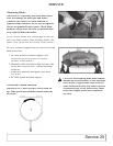
4. Adjust center link so rear of cutter is approxi-
mately 2 inches (51 mm) higher than front.
NOTE:
The rotary cutter should be operated at the highest
position which will give optimal cutting results. This
will help prevent the blades from striking the ground,
reducing blade wear and undue strain on the cutter.
For best results under heavier cutting conditions,
always tilt the rotary cutter approximately 2 inches
(51mm) lower in the front. This tilt decreases horse-
power requirements and increases potential ground
speed. When fine shredding is desired, adjust rotary
cutter deck level or slightly lower in the rear. This
will keep the foliage under rotary cutter until thoroughly
shredded. More power is required for shredding.
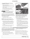
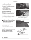
5. Lower tailwheel to support rear of the cutter.
6. Install bolt, washers and lock nut (A) into one of
seven holes (C) that aligns with hole in wheel support.
7. Reinstall bolt, washers and lock nut. Tighten lock
nut. (A)
NOTE:
The tailwheel supports the rear of the machine and
the draft links support the front to allow the cutter
to follow the ground contour.
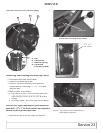
Each rotary cutter can be adjusted to several cutting
heights from 1.5 inches to 9 inches of cutting height by
moving the rockshaft control lever in conjunction with
moving the tailwheel adjustment bolt among the height
adjustment holes (see photo above)
IMPORTANT: Loosening the center link may allow
the driveline to contact the cutter frame or tractor
tires to contact the foot guards or chain shield. Raise
the cutter slowly and check for interference. Lengthen
tractor lift links to provide clearance to full height.
NOTE: Lift height may also be limited by installing
stops on rockshaft control lever bracket.
8. Lengthen tractor lift links, if necessary, to
provide
clearance.
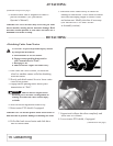
9. For cutter equipped with
iMatch Hitch, adjust tractor
center link until bushing is
centered in slot.
OPERATION
18 Operation
B
A
A-B Lock Nut, Washers, Bolt C- Adjustment hole
C
DANGER
!