Attaching 15
ATTACHING
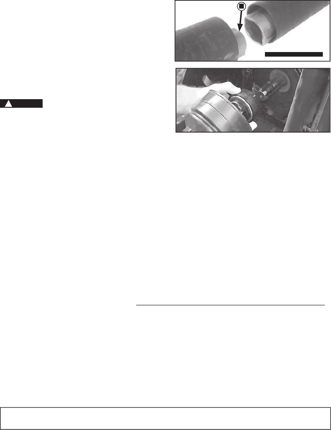
• Assembling PTO Driveline Telescoping
Members (If Necessary)
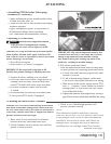
1. Apply multipurpose grease around outside surface
of inner driveline tube (A).
2. Align driveline halves and assemble telescoping
members together.
3.Apply multipurpose grease, or equivalent, to
all lubrication fittings before operating.
(See Lubrication and Maintenance section.)
• Attaching PTO Driveline
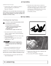
Shut off tractor engine before attachi
ng
PTO driveline. Entanglement in rotating
drive
line can cause serious injury or death.
IMPORTANT: Keep driveline and powershaft splines
clean of paint, dirt and chaff. Apply John Deere SD
POLYUREA Grease or equivalent on tractor PTO shaft
before attaching PTO driveline.
1. Shut off tractor engine.
2. Raise tractor PTO shield, if equipped.
IMPORTANT: Do not use bell on driveline to lift
driveline into position. Damage to shielding can occur.
3. Support driveline, cradling it in your hand.
4. Pull collar back toward cutter. Align splines by
rotating cutter driveline. Push driveline onto
tractor PTO shaft until collar snaps into place.
5. Pull back on shield to make sure driveline
is locked.
6. Do not pull back on collar, this will release latch.
7. Lower tractor PTO shield, if equipped.
IMPORTANT: Slip clutch components must be free
to rotate when necessary. After thirty days or more,
linings of slip clutch may draw moisture. Linings
may bond to metal parts causing slip clutch to be
ineffective, resulting in machine damage.
8. Slip clutch operational check.
After the implement has been stored for thirty days
or more perform the following operational check.
a. Loosen bolts and lock nuts progressively until
tension is relieved.
b. To aid in determining slippage, scribe/mark
a line across clutch plate and Belleville Spring.
c. With tractor at idle speed, engage tractor PTO
drive 2 - 3 seconds. Clutch should slip without
turning blades. If clutch does not slip, contact
your authorized dealer.
d. Tighten bolts and lock nuts progressively, leaving a
gap of 4mm, between clutch plate and Belleville spring.
A-Inner Driveline Tube
A
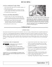
• Checking Driveline/Cutter Clearance
IMPORTANT: Prevent driveline damage from contact
with frame or machine damage from contact with trac-
tor tires. Raise cutter slowly and check for interference.
If necessary, shorten center link or lengthen lift links to
provide clearance to full lift height.
1. Raise cutter slowly and check for clearance
between driveline shield and cutter deck.
2. Check clearance between tractor tires and foot
guards or chain deflector.
3. Check to see if hitch height position will
provide clearance desired.
NOTE:
Final adjustments should be made before operating
cutter. See ADJUSTING CUTTING HEIGHT AND ANGLE
in Operating the Cutter section.
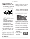
Center link should be
installed in lowest hole at tractor end if there are
multiple holes. Lift height may also be limited by
installing stops on rockshaft control lever bracket.
(continued on next page)
DANGER
!


