


20 Dealer Service
5WPMAN0705 (Rev. 5/9/2008)
DEALER SERVICE
The information in this section is written for dealer ser-
vice personnel. The repair described here requires
special skills and tools. If your shop is not properly
equipped or your mechanics are not properly trained in
this type of repair, you may be time and money ahead
to replace complete assemblies.
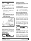
Before working underneath, read manual
instructions, securely block up, and check stability.
Secure blocking prevents equipment from drop-
ping due to hydraulic leak down, hydraulic system
failure, or mechanical component failure.
Keep all persons away from operator control
area while performing adjustments, service, or
maintenance.
Always wear relatively tight and belted clothing
to avoid entanglement in moving parts. Wear
sturdy, rough-soled work shoes and protective
equipment for eyes, hair, hands, hearing, and head;
and respirator or filter mask where appropriate.
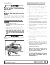
BLOCKING METHOD
See instructions on page 14.
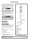
BLADE SPINDLE REPAIR
Spindle repair requires special skills and tools. If your
shop is not properly equipped or your mechanics are
not trained in this type of repair, you may be time and
money ahead to use a new spindle assembly.
For reference, the grease fitting is in the top of the spin-
dle shaft.
Permatex
®
3D Aviation Form-A-Gasket or equivalent is
recommended as a sealant.
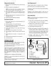
Remove Spindle
1. Remove belt shields from deck.
2. Remove belt.
3. Remove blade from spindle assembly.
4. Remove nuts (6) and bolts (9) that secure spindle
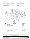
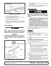
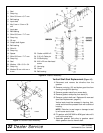
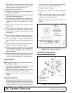
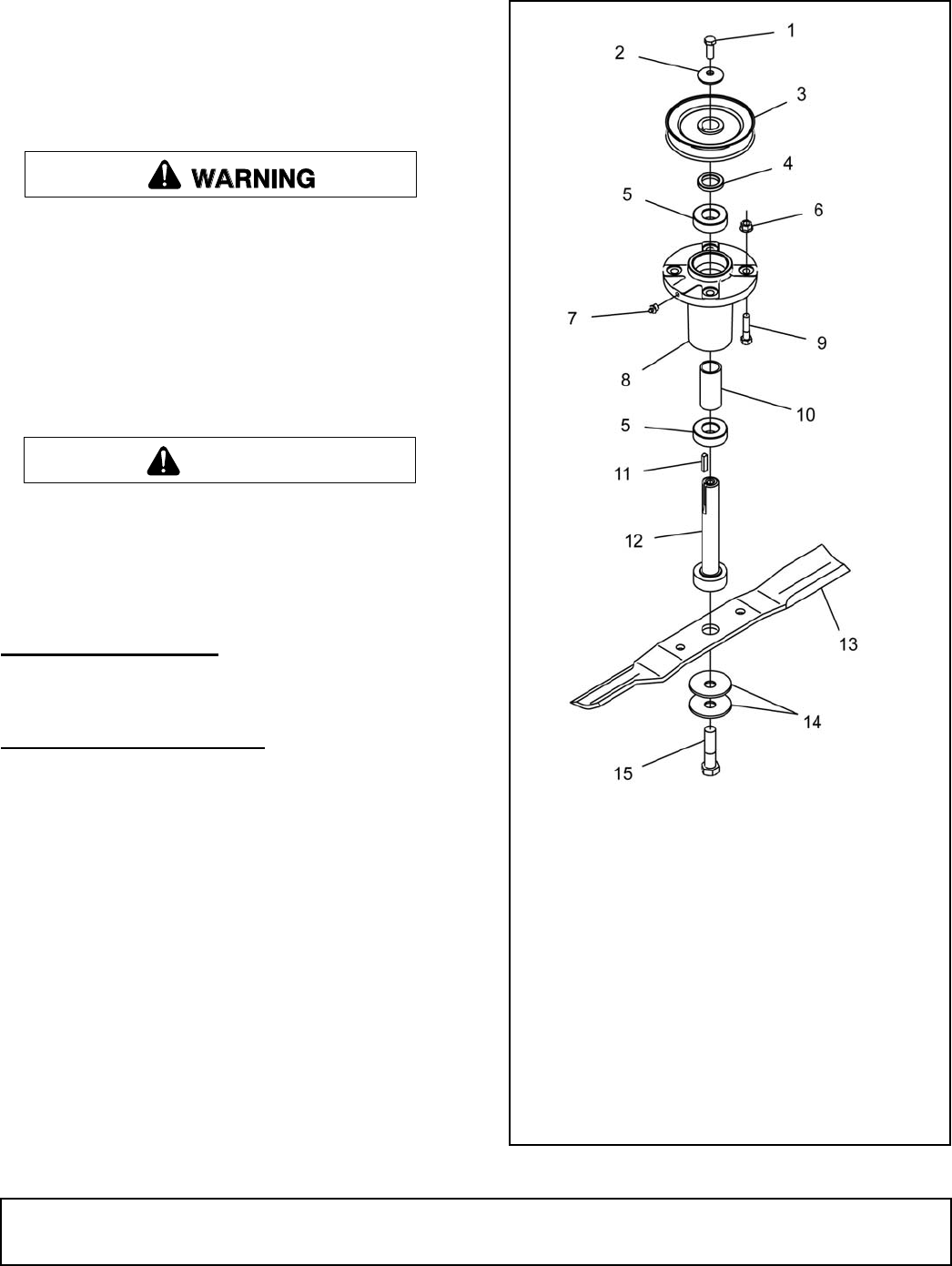
to mower. (See Figure 12.) Figure 12. Blade Spindle Assembly
CAUTION
1. 3/8 NF x 1 HHCS GR5
2. Cup washer
3. Sheave
4. Spacer
5. Spindle bearing
6. 3/8 NC Flange lock nut
7. 1/4 Tapered grease fitting
8. Spindle housing
9. 3/8 NC x 1-1/2 HHCS GR5
10. Spacer
11. Square key
12. Shaft assembly
13. Blade kit
14. Cup washer
15. 5/8 NF x 2 HHCS GR5
CD6308