


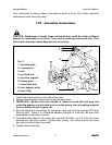
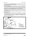
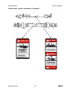
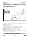
7. Bolt up the top hitch arms (see #4, fig. 2 & 3) to the outside of the rear support
plates (see #10, fig. 3) on the rear of the mower.
8. Bolt up the top hitch supports to the inside of the linking plates (see #6, fig, 2). Use
the top holes (see fig. 2).
9. Bolt up the top hitch plate (see #1, fig. 2 & 3) with the bolt M16x140 (see #3, fig. 2).
It should be bolted as follows: bolt, top hitch support, top hitch arm, top hitch plate,
spacer, top hitch arm, top hitch support, locknut M16. Tighten the locknut down
securely, the top hitch plate should be able to swivel 360° (see fig. 2).
10.Install the lower hitch arms (see #7, fig. 2) in the lower hole of the linking plates
(see #6, fig, 2). If assembled properly, the hitch plates will rest on the “thumb” of the
linking plate when down. Tighten the bolts holding the lower hitch arms. Be sure
they are able to swivel.
11.Grease wheels, wheel arms, and spindles. Check the gearbox for oil. It should be
approximately ½ filled.
12.Install driveline and ensure it has at least 2” from bottoming out in its shortest
working position and has the minimum 6” overlap in its longest working position.
Refer to Section 4.06
1
of this manual, if it is determined that the driveline is too long
and needs to be shortened. Contact your local dealer if it is determined that the
driveline is too short for your tractor .
G
ROOMING
M
OWER
O
PERATOR
’
S
M
ANUAL
G
ENERAL
I
NFORMATION
6 FRONTIER
1
See Section 4.06 - Driveline, for instructions on how to determine correct driveline length and
procedures for shortening the driveline.
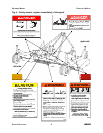
Fig. 3
1
1. top hitch plate
5. top hitch support
4. top hitch arm
10. rear support plate
5
4
10