


28 Assembly
5WPMAN0242 (Rev. 5/2/2008)
ASSEMBLY INSTRUCTIONS
DEALER SET-UP INSTRUCTIONS
Assembly of this mower is the responsibility of the
Woods dealer. If should be delivered to the owner com-
pletely assembled, lubricated, and adjusted for normal
cutting conditions.
Complete check lists on page 32 when you have com-
pleted the assembly.
The mower is shipped partially assembled. Assembly
will be easier if components are aligned and loosely
assembled before tightening hardware. Recommended
torque values for hardware are located on page 46.
Select a suitable working area. Open parts boxes and
lay out parts and hardware to make location easy.
Refer to illustrations, accompanying text, parts lists and
exploded view drawings.
Never go underneath equipment (lowered to the
ground or raised) unless it is properly blocked and
secured. Never place any part of the body under-
neath equipment or between moveable parts even
when the engine has been turned off. Hydraulic
system leak down, hydraulic system failures,
mechanical failures, or movement of control levers
can cause equipment to drop or rotate unexpect-
edly and cause severe injury or death. Follow Oper-
ator's Manual instructions for working underneath
and blocking requirements or have work done by a
qualified dealer.
Always wear relatively tight and belted clothing
to avoid entanglement in moving parts. Wear
sturdy, rough-soled work shoes and protective
equipment for eyes, hair, hands, hearing, and head;
and respirator or filter mask where appropriate.
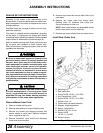
Remove Mower from Crate
1. Select a suitable working area.
2. Remove sides and top of mower shipping crate.
3. Remove lag screws and shipping brackets that
secure mower to crate base. Replace hardware
that is required for the unit.
4. Remove driveshaft, cone shield and discharge
chute wired to mower deck.
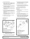
5. Remove lag screws that secure offset links to the
crate base.
6. Remove rear caster arms from mower deck.
Remove extra 1/2" hardware from caster arm.
Save all hardware for later use.
NOTE: Rear caster wheels are assembled upside
down in rear caster arms for shipment.
7. Remove rear caster wheels from rear caster arms.
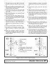
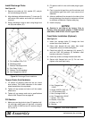
Install Rear Caster Arm
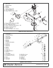
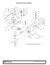
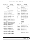
Figure 27. Rear Caster Assembly
CAUTION
B. Mounting lug
3. Rear caster arm
4. Screw, HHCS 1/2 NC x 1-3/4 GR5
5. Nut, Flanged lock 1/2 NC
6. Screw, HHCS 1/2 NC x 2-1/4 GR5
7. Washer, Lock 1/2"
8. Caster shaft and wheel assembly
9. Spacers, Height adjustment
10. Spring, Compression
11. Washer, Flat .50 x 10 Ga
12. Screw, HHCS
1/2 NC x 1-1/4 GR5
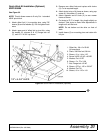
13. Shield, Left belt