


attached and is carried by the transport tires. These three components are held together
by numerous large bolts M18x45. The main objective of the frame carrier of the Flex
mower is to allow the three mowing units to follow the ground contour and float freely
and independently from each other.
In order to achieve a perfectly uniform cut, it is important that all three mowers rest
completely on the ground at all times with all of their four wheels touching. This ensures
that each individual mower cuts level and maintains a uniform cut along the entire
cutting width of the machine. The free floating concept is indispensable when cutting
with gang mowers.
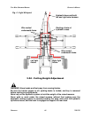
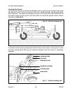
The three units are connected to the frame by a double pivot setup. The first pivot point
is at the overlapping pipes of the frame itself and the second in the telescopic arm
attaching the mowers to the frame. This articulating free floating system would not be
possible without the complete release of all hydraulic pressure as you will see with the
other important frame adjustments.
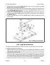
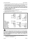
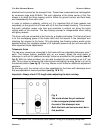
Telescopic Arms
The two wing mowers are connected to the frame with two adjustable telescopic arms
10
each. This unique feature, available only on our mower, allows the wing decks to
telescope in and out for additional overlap. Holes are provided for this purpose (see #1,
fig. 8). With the holes provided, you are able to adjust the cut overlap by up to 6” per
side. This is done by removing the retaining bolt and sliding the wing frame in or out to
the desired position (see fig. 8). You may choose to drill holes for additional adjustment
positions.
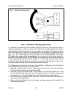
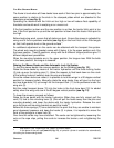
As the wing units, the central unit is also assembled to the frame with telescopic arms
that are adjustable in several positions (see fig. 10 & 11).
Important: Always check PTO length when adjusting the deck overlap.
OPERATION 22 FRONTIER
F
LEX WING GROOMING MOWERS OPERATOR’S MANUAL
10
See Section 4.06 - Drivelines and Center Gearbox Timing, prior to adjusting overlap width.
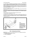
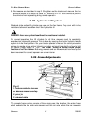
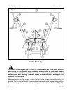
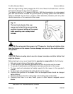
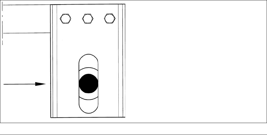
Fig. 9
The arrow shows the pin centered
in the rectangular plates bolted to
the end of the telescopic arm.
Both the front and rear arm must be in
this position.