


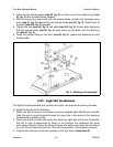
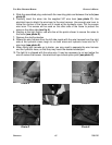
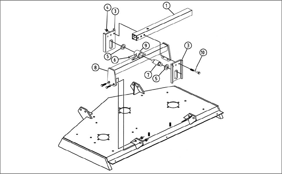
3. Place the two formed plates (see #3, fig. 3) on either end of the attaching pin (see
#7, fig. 3) with the bend facing outward.
4. With the wing arms down level with the mower decks, position the telescopic wing
arms (see #1, fig. 3) between the two formed plates (see #3, fig. 3). Attach them to
the bolts (see #10, fig. 3) provided.
5. Tighten the nuts (see #4, fig. 3) and bolts (see #10, fig. 3). Ensure after tightening
that the formed plates (see #3, fig. 3) move freely up and down over the attaching
pin (see #7, fig. 3).
6. Using the grease fitting on the hitch (see #6, fig. 3), grease the attaching pin and
formed plate.
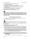
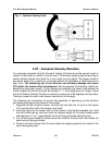
3.03 - Light Kit Installation
The light kit comes standard and contains two lights, two brackets and wiring harness.
To install the light kit do the following:
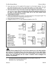
1. Attach the light fixtures to the bracket using the supplied bolts M6x25 and nuts M6.
Note: Be sure to route the wires through the large hole in the center of the mounting
bracket before installing bolts.
2. Route the strand of wires with green wire down the right side of the unit (remember
that left or right is determined by facing in the direction the implement will travel
when going forward). Route the strand of wires with yellow wire down the left side of
the unit. Do not install the wire ties. This will be done later in the assembly process.
3. Plug the wire harness to the wire harness on the light fixture (see photo A).
OPERATION 14 FRONTIER
F
LEX WING GROOMING MOWERS OPERATOR’S MANUAL
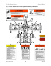
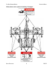
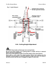
Fig. 3 - Mowing unit assembly.