


Assembly 35
5WPMAN0183 (Rev. 4/25/2008)
4. Adjust tractor hitch bracket on trailer frame so the
trailer is level when attached to the tractor.
5. Pin the mower to the tractor with a locking type
hitch pin.
6. Attach drive shaft to tractor PTO. Make sure lock
collar engages securely.
7. Attach end of transport lock release rope to a loca-
tion on the tractor within easy reach of the operator
and away from driveline.
NOTE: When routing the rope, do not route
through the hydraulic hose guide and do not allow
rope slack to drop between the driveline shields
and the gearbox rotating shafts.
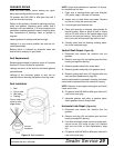
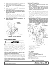
8. Attach towing safety chain to tractor drawbar as
shown in Figure 30.
Figure 30. Tow Chain Installation
Attach Hydraulic Hoses
Air in hydraulic systems can cause erratic oper-
ation and allows loads or equipment components
to drop unexpectedly. When connecting equipment
or hoses or performing any hydraulic maintenance,
purge any air in hydraulic system by operating all
hydraulic functions several times. Do this before
putting into service or allowing anyone to
approach the equipment.
Attach the mower hydraulic hose to the tractor port.
Hydraulic quick coupler is not supplied.
NOTE: The mower hydraulic system should have been
filled at the factory. Always assume it is empty. Fully
purge air and fill the hydraulic system by raising and
lowering wings several times while hooked to a tractor
hydraulic supply. Keep all personnel away while raising
and lowering.
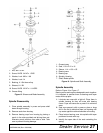
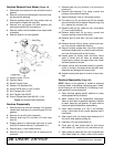
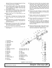
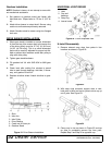
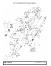
Lighting Kit Installation
1. Install electronic module to rear cylinder mount
using #10 screws (8).
2. Route wires as shown. Do not install wire ties at
this time. Be sure wire labeled “Left” is routed to left
light. Pass wires over axles, under deck support
platform, and up the outside rear corner.
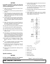
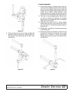
3. Install left and right light brackets as shown using
3/8" bolts (11), washers (13), and nuts (12). If more
clearance is desired between light brackets and
tires, add more 3/8" flat washers. Be sure wires
pass through the corners before tightening light
brackets.
4. Connect lights to wiring harness.
5. Starting at each light, pull the wire tight and install
wire ties as shown. Any extra slack in the wiring
harness should be located at the center of machine
near the electronic module. Route main wire along
hydraulic hose and secure to hose using wire ties.
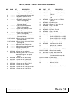
1. Left hand light (not shown)
2. Right hand light
3. Left light bracket (not shown)
4. Right light bracket
5. Wire harness
6. 14" Tie strap
7. 7" Tie strap
8. #10 x 1/2" Tapping screw
9. 1/4 NC x 1" Hex head cap screw GR5
10. 1/4 NC Lock nut
11. 3/8 NC x 1" Hex head cap screw flanged GR5
12. 3/8 NC Flange lock nut
13. 3/8" Standard flat washer
Figure 31. Lighting Kit Installation
(229 mm)