


9English
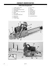
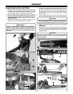
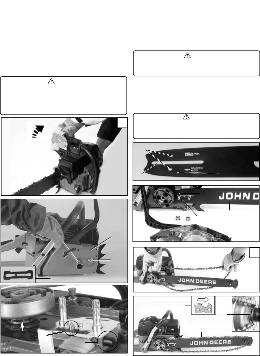
Assembling the Bar and Chain
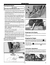
1. Ensure that the chain brake is not set by pulling the chain
brake lever / hand guard towards the front handle as shown
in Illustration (A). Refer to Safety-Chain Brake and Opera-
tion-Chain Brake Sections for additional information.
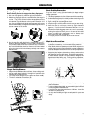
2. Remove the two (2) bar nuts (B) and the clutch cover (C).
3. Remove and discard the plastic shipping spacer (D) that
has been installed on the bar studs in place of the bar for
shipping purposes.
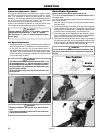
4. Adjust the chain tensioning pin (E) fully towards the rim
sprocket (F) using the chain tensioning screw (G).
ASSEMBLY
WARNING
Check the chain tension frequently when operating the
chain saw. Never touch or adjust the chain while the
motor is running. The saw chain is very sharp, always
wear protective gloves when performing maintenance to
the chain.
5. The guide bar contains a bar stud slot (H) that fits over the
bar studs. The guide bar also contains two chain tensioning
pin holes (J) which fit over the chain tensioning pin and
two lubrication holes (K). The bar is reversible and either
tensioning pin hole may be utilized with the chain
tensioning pin.
6. Place the guide bar (L) onto the bar studs (M) so that the
chain tensioning pin (E) fits into the chain tensioning pin hole.
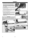
7. Position the bar tip through the chain loop as shown in
Illustration (
N).
8. Fit the chain (P) over the rim sprocket (F) and into bar groove.
The cutters on the top of the guide bar should face toward the
bar tip, in the direction of the chain rotation. See insert (Q) in
Illustration below.
CAUTION
Failure to assure that the chain tensioning pin is in the
chain tensioning pin hole will result in severe damage to
the chain saw during reassembly of the clutch cover.
L
E
B
C
P
D
Q
H
J
N
F
M
CAUTION
Severe damage can occur to the rim sprocket, clutch drum,
guide bar and chain, if the chain is not correctly seated into
the rim sprocket.
K
A
E
G
F