


D
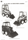
60, 90, and 125 Skid-Steer Loaders
30-200-7
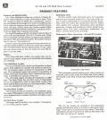
Easy Servicing-Continued
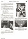
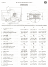
(90 Skid-Steer Loader shown)
The motors are under the floor panel on the Model 90.
The reservoir is located in the crossbeam between the boom
tower and in the boom towers. A convenient fill tube is
located on top of the crossbeam with a visible sight gauge
showing when the reservoir is full or when additional fluid is
needed. Access to the motors on the Model 90 is obtained by
pulling two clip pins to remove the seat, and removing four
capscrews to remove the one-piece T-barcowl and floor pan-
el.
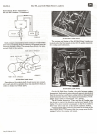
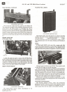
ENGINESLIDE RAIL
(125 Loader Only)
A slide rail system is used to remove the 125 Skid-Steer
Loaderengineand hydrostatic pumps for major repair work.
The time required to remove these components from major
competitive loaders can take up to twice as long. The slide
rail feature savesthe operator costly downtime by allowing
repair work to be done outside of the loader.
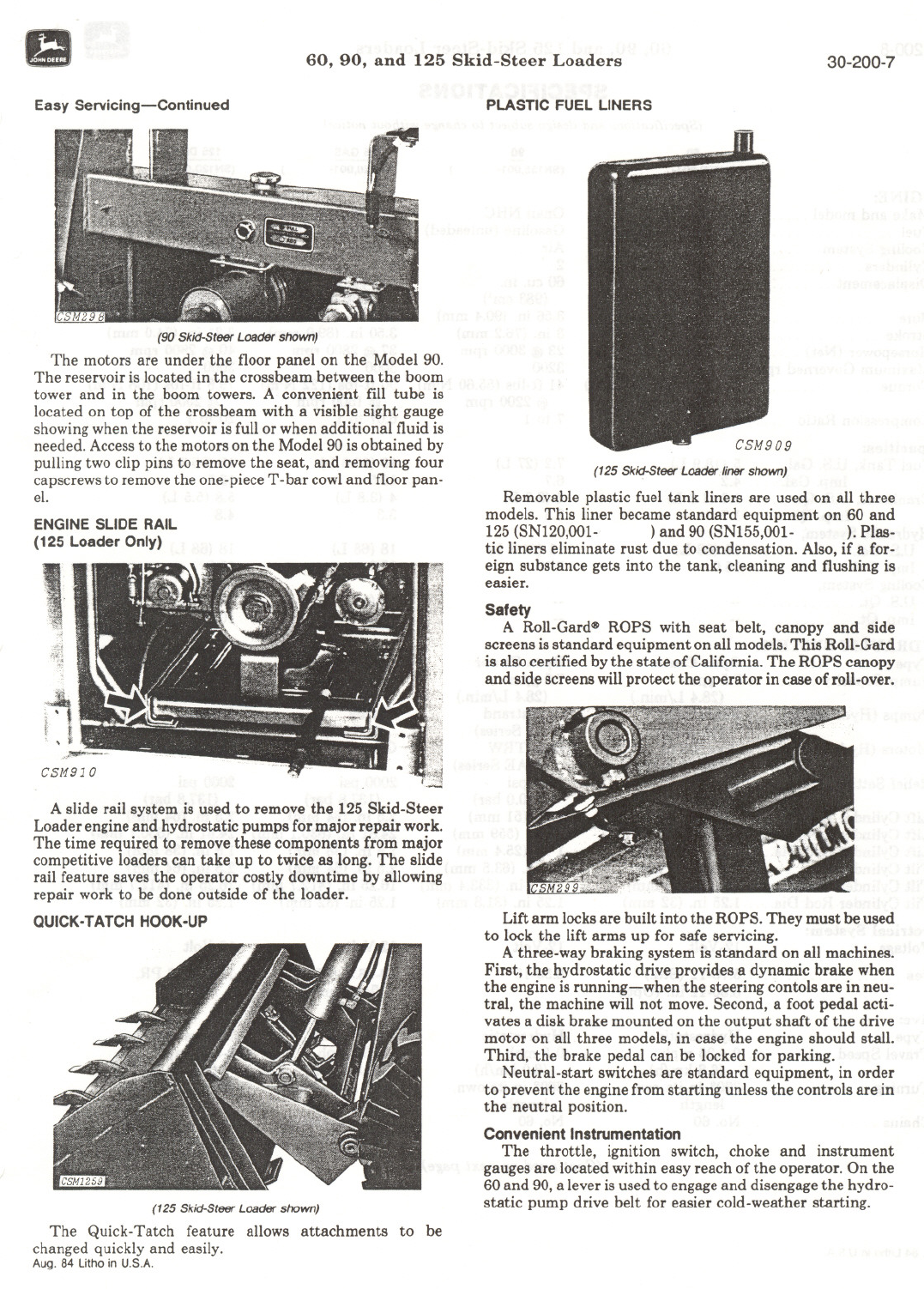
aUICK.TATCH HOOK.UP
(125 Skid-SteerLoader shown)
The Quick-Tatch feature allows attachments to be
changed quickly and easily.
Aug. 84 Litho in U.S.A.
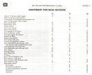
PLASTIC FUEL LINERS
(125 Skid-Steer Loader liner shown)
Removable plastic fuel tank liners are used on all three
models. This liner became standard equipment on 60 and
125(SNI20,OOI- )and 90 (SNI55,OOI- ). Plas-
tic liners eliminate rust due to condensation. Also, if a for-
eign substance gets into the tank, cleaning and flushing is
easier.
Safety
A
Roll-Gard~ ROPS with seat belt, canopy and side
screens is standard equipment on all models. This Roll-Gard
is also certified by the state of California. The ROPS canopy
and side screens will protect the operator in case of roll-over.
Lift armlocksare built into the ROPS. They must be used
to lock the lift arms up for safe servicing.
A three-waybrakingsystemisstandardon allmachines.
First, the hydrostatic drive provides a dynamic brake when
the engineis running-when the steering contoIs are in neu-
tral, the machine will not move. Second, a foot pedal acti-
vates a disk brake mounted on the output shaft of the drive
motor on all three models, in case the engine should stall.
Third, the brake pedal can be locked for parking.
Neutral-start switches are standard equipment, in order
to prevent the enginefrom starting unless the controls are in
the neutral position.
Convenient Instrumentation
The throttle, ignition switch, choke and instrument
gaugesare located within easy reach ofthe operator. On the
60and 90,a leveris used to engageand disengage the hydro-
static pump drive belt for easier cold-weather starting.