


D
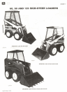
60, 90, and 125 Skid-Steer Loaders
30-200-5
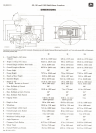
Hydrostatic Drive Operation-125 Loader
FLYWHEEL
SPLINED MDUNTING
HUB PLATE
/£1/
&~
'\ ENGINE
FLYWHEEL
HOUSING
CSM951
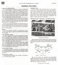
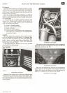
Engine power is transmitted to the hydrostatic, variable-
displacement-piston pumps. This is achieved by coupling
the rear hydrostatic pump input shaft with a splined hub
that is bolted to the engine flywheel.
PUMP
-.;..-:'.:~- ...,
--.(.- -\
C7T\I---~~'
----"-:"" I _~I
-- -- --
-- --
"'" -.. - \ I
"'-'::-: ,<1-
,
-)
~
\ ' \
,~ --:::::---- \ \ \
~ z.'>"'-- -- \ \ \
\\ ~-,--""::::...~~ \ \
" I,' I "'
2\
-- "; \ ~
" I " ..
\
,. '.."~- I,.?-
\'! " \I, I__~__-
~ 'I 1.-- --,..
\
t \ ---~ :-
\~- ".-~ -
\ t-:/
\ " --,
/ , ~-
'/ I'I:"'~'
I 11,-""
I '/
1 II
1
I
I
I \ I,
'\'
-,.,' ~\
\
"I
/~__~', t \ \ \..-
- :'! '\ \ \.
' I
-../;--~
CSM73'S
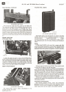
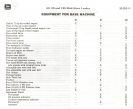
The front pump is coupled in tandem to the rear pump by
a splined input shaft. Each pump is connected by hose-
routing to a fiXed-displacement-piston hydrostatic motor.
Hydraulic fluid isdrawn bythe pumps from the oilreservoir
through a filter. The pumps then deliver the fluid, under
pressure, to the motors through the dark colored hoses.One
hose is for forward motion and one is for rearward motion.
Aug, 84 Litho in U,S,A,
,~~ --' ==-,-~,,=-,-~~,
.' " i~""-,
" - - - -,- - - ..:t~.
't ~ - 1_/it} '--
, ---- -
(-- --'I
'- -
',-"-
,-..""-.. '
--- - ,
- ,--- -~
" ,'r'
y" ,:
, 'I . -;',
", ,;', :,' "
'" \"
, c..:-::
\
,I
.S' - ,
;:' -..
II
'~(
\ \ \ ""'-",
"" ',_~"":"r-:::::::" -~-::.-:.-
",...' ..,.~'C~'- '",;:::- .,..
-"'/' " .
- --- \"---~'i
" /.. \,1 "
CSM952 I -' \ ,\~\ \~"'-
- \,,', "--"!"'~~'
\ " -',
(\ \
~
I I ,)
, ,\
I, ~~ ~
,
I 'I -'
~ .~
~I/, ~ .-
-<
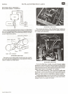
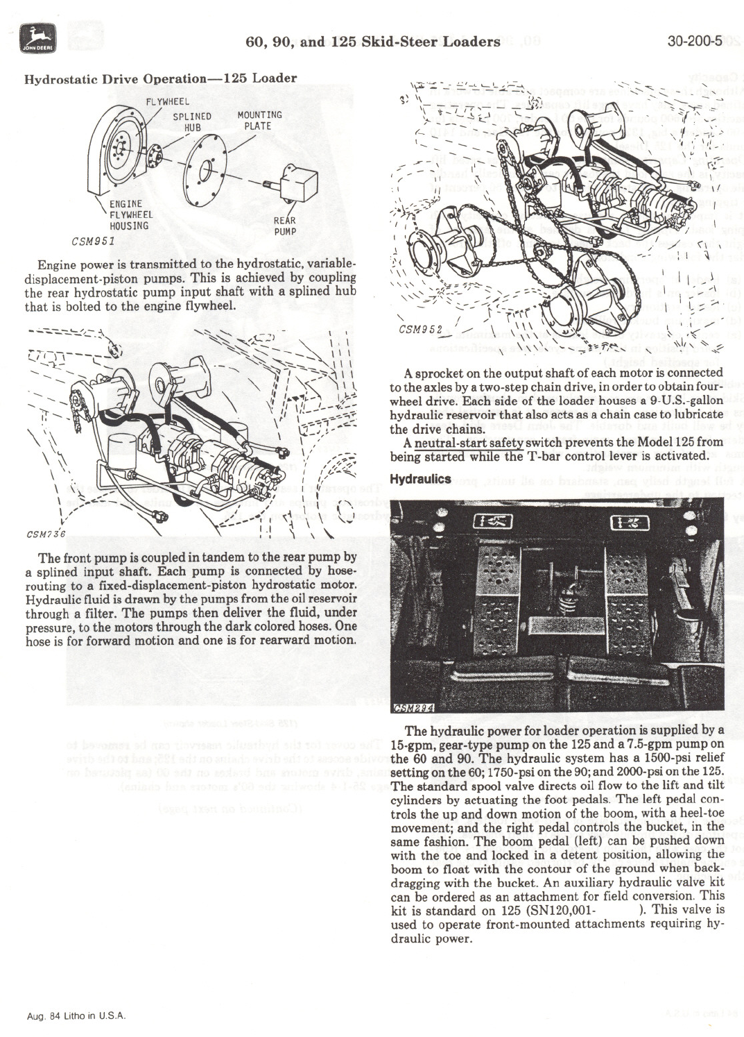
A sprocket on the output shaft of each motor is connected
to the axles by a two-step chain drive, in order to obtain four-
wheel drive. Each side of the loader houses a 9-D.S.-gallon
hydraulic reservoir that also acts as a chain case to lubricate
the drive chains.
A neutral-start safety switch prevents the Model 125 from
being started while the T -bar control lever is activated.
Hydraulics
The hydraulic power for loader operation is supplied by a
15-gpm,gear-type pump on the 125and a 7.5-gpmpump on
the 60 and 90. The hydraulic system has a 1500-psirelief
setting on the 60;1750-psion the 90;and 2000-psion the 125.
The standard spool valve directs oil flow to the lift and tilt
cylinders by actuating the foot pedals. The left pedal con-
trols the up and down motion of the boom,with a heel-toe
movement; and the right pedal controls the bucket, in the
same fashion. The boom pedal (left) can be pushed down
with the toe and locked in a detent position, allowing the
boom to float with the contour of the ground when back-
dragging with the bucket. An auxiliary hydraulic valve kit
can be ordered as an attachment for field conversion. This
kit is standard on 125 (SNI20,OOI- ). This valve is
used to operate front-mounted attachments requiring hy-
draulic power.