


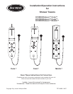

Jacuzzi Whirlpool Bath: Shower Towers Page 10 FZ71000B • 09/07
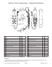
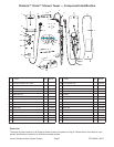
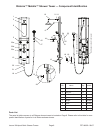
NOTE: Parts with item number listed are included.
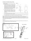
Determine the installation height of the shower tower. The height of the top row of the body jets should be level
with the users’ shoulders. Place a mark on the wall at the top of the unit when the top jets are at the desired
position. Begin installation using the following instructions.
Finish Wall Preparation
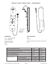
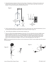
1. Drill three holes 1/4" diameter by 1-3/8” deep in
the wall at the locations and dimensions shown
in Figure 1.
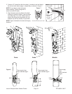
2. Insert plastic anchors (18) into each of the
holes, then mount the wall mount xing rods (7)
to the wall using the M4.2x35mm screws (8),
see Figure 2.
NOTE: Figure 3 is for Metallo only.
3. The User can adjust the height. Drill four holes at 1/4" diameter by 1-3/8" deep.
The distance of the holes are 1-3/16" and 35-3/16" apart. Insert the anchor (18)
to the holes. Then use the screw (8) to x the location of the hanger on the wall,
see Figure 3.
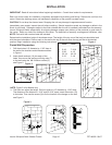
Each unit arrives ready for installation, completely equipped with plumbing and ttings. Remove the unit from the
carton. Retain the shipping carton until satisfactory inspection of the product has been made.
CAUTION: Do not drop the shower tower. Dropping the unit may damage its appearance and function.
Immediately upon receipt, inspect the unit before installing. Should inspection reveal any damage or defect in the
nish, do not install. Damage or defect to the nish claimed after the unit is installed is excluded from the warranty.
Jacuzzi Whirlpool Bath's responsibility for shipping damage ceases upon delivery of the products in good order to
the carrier. Refer any claims for damage to the carrier. For denitions of warranty coverage and limitations, refer
IMPORTANT: Read all instructions before beginning installation. Consult local codes for requirements.
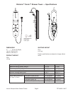
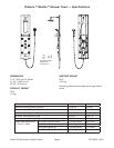
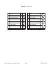
Ovale Onda
- - - - - - - - - - - - - - - - -
A 5-1/8 7-3/16
B 2-3/8 4-1/2
C 33-1/4 46-1/2
D 3-1/2 2-1/4
- - - - - - - - - - - - - - - - -
Measurements in inches
Figure 2
Figure 3
1-3/16"
35"
1-3/16"
8
18
7
1-3/16"
35-3/16"
INSTALLATION
Figure 1
A
B
C
D
To
p
o
f U
n
it