


SECTION 2—PARTS AND INSTALLATION
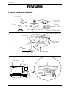
Side Entry Whirlpool Tub 16 Part No 1118387
Securing Tub
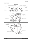
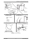
NOTE:Forthisprocedure,refertoFIGURE 2.2.
1. Setthetubinplace.
2. Ensureplumbingandelectricalhook‐upshavebeeninstalled.RefertoElectricaland
PlumbingHook‐upLocationsontheTubonpage 17,ElectricalInstallationonpage 17
andPlumbingInstallationonpage 20toensuretheproperhook‐upshavebeen
installedbeforesecuringthetub.
3. Marklocationofanchorholes,usingpre‐drilledholesinlegmountingpadsasa
template.
4. Movetubawayfrommountingarea.
ƽ WARNING
Protective eye wear MUST be worn when drilling to avoid possible eye injury.
5. Drillanchorholesinfloor.Usejack‐drillandcarbidebitinconcreteorawoodbitfor
woodfloors.
6. Repositionthetubinmountingarea,aligningtheholesinthelegmountingpadswith
theholesdrilledinSTEP4.
ƽ WARNING
DO NOT adjust height of legs more than 1 inch (25.4 mm) for Model 3650 or 2
inches (50.8 mm) for Models 3600 and 3600XL; leg will disassemble from leg
mounting pad and serious injury may occur.
7. Levelthetubbyadjustingthetelescopiclegseitherupordown,usingawrench,to
arriveatthedesiredheight.
8. Checktomakesuretubislevelbyplacingalevelonthefrontandsidesofthetub.
9. RepeatSTEPS6and7untiltubislevel.
10. Securelegstofloorusingfastenersappropriatetothefloormaterialandinkeeping
withanylocalcodes.
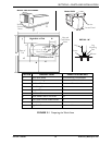
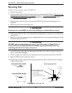
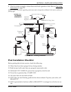
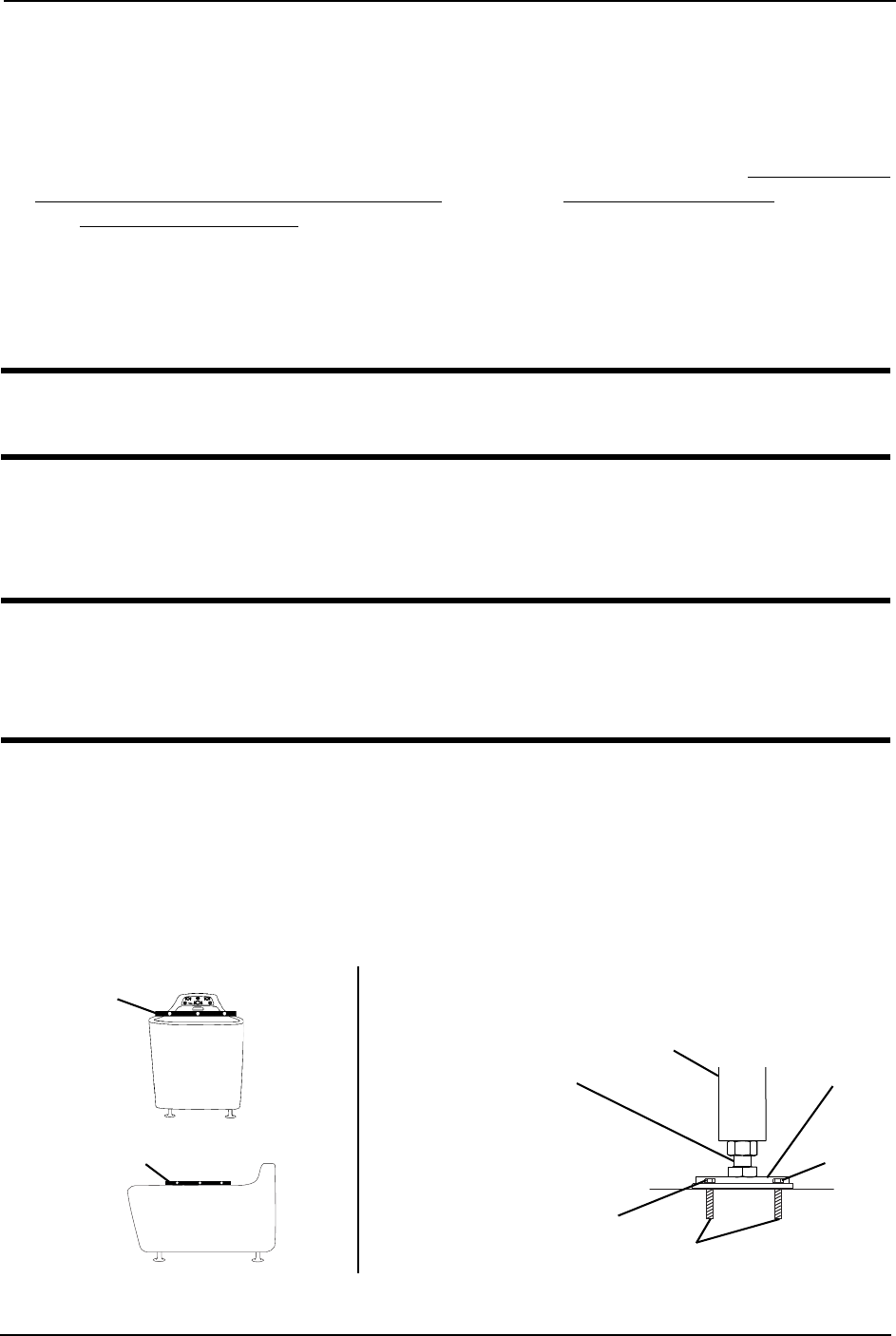
FIGURE 2.2 Securing Tub
LEVELING END TO END
LEVELING SIDE TO SIDE
Level
Level
Lag
Bolt
Leg
Leg
Mounting
Pad
Anchors
Maximum Adjustment
• 1-inch (25.4 mm) for
Model 3650)
• 2-inch (50.8 mm) for
Models 3600 and 3600XL
Securing Legs to Floor
Lag Bolt