


Product Specifications
Thermal and Mechanical Design Guidelines 11
2 Product Specifications
This chapter provides the package description and loading specifications. The chapter
also provides component thermal specifications and thermal design power descriptions
for the (G)MCH.
2.1 Package Description
The (G)MCH is available in a 34 mm [1.34 in] x 34 mm [1.34 in] Flip Chip Ball Grid
Array (FC-BGA) package with 1202 solder balls. The die size is currently 9.6 mm
[0.378in] x 10.6 mm [0.417in]. A mechanical drawing of the package is shown in
Figure 9, Appendix B.
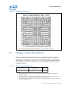
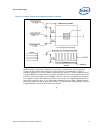
2.1.1 Non-Grid Array Package Ball Placement
The (G)MCH package uses a “balls anywhere” concept. The minimum ball pitch is
0.8 mm [0.031 in], but ball ordering does not follow a 0.8-mm grid. Board designers
should ensure correct ball placement when designing for the non-grid array pattern.
For exact ball locations relative to the package, contact your Field Sales
Representative.