


PAGE 2 OF 4 651747ĆXĆB
POWER
SUPPL
Y AND INST
ALLATION
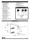
NOTE: The power supply cable is not furnished with the unit and must be
supplied by the customer.
Do not useneutral as earthground. Asinglephase power/earth ground
is required. Ifthis is not available,use a transformer to obtainsingle phase
power.
Provisions shouldbemade fora quickdisconnector shutĆoffofallelectrical
power to this unit.
All wiring must comply with all local and / or national electrical codes.
• Electrical codes thatapply must be strictly adheredto. Failure todo so
may lead to shock hazard or serious injury.
• Somelocal electricalcodes mayrequiretheinstallationof rigidconduit.
• The installer of this system assumes full responsibility for compliance
with these codes.
• Aro is notresponsible foraccidents resultingfrom improperinstallation
of components or hardware.
• No electrical power shouldbe in the systemat the timethe cover isreĆ
moved.
AIR
AND LUBE REQUIREMENTS
Commonly used solvents and their lowest boiling points as pertains to the
Aro free flow system:
Hydrocarbons (Petroleum Naphthas)
Boiling Point _ F(_ C) k
VM & P 244 (118)
Mineral Spirits 314 (157)
Odorless Mineral Spirits 353 (178)
Aromatics (Terpenes)
Benzene 172 (78)
Toluene 230 (110)
Xylene 281 (138)
Gum Turpentine 311 (155)
Dipentene 347 (175)
Alcohols
Methanol 147 (64)
Isobutyl Alcohol 223 (106)
Nybutyl Alcohol 241 (116)
Keytones
MEK 174 (79)
Acetone 122 (50)
Diacetone 284 (140)
k International Critical Tables (ref.)
OPERATING INSTRUCTIONS
STARTĆUP PROCEDURE
1. Fill the system with fluid.
2. Circulate the fluid thru the system.
CAUTION Power should never be on when there is onlysolvent
in thesystem. Solvents canexpand if there isno circulation,causing
excessive and hazardous pressure in the system.
3. Turn the power on.
4. Set the thermostat justbelowthe boilingpoint ofthe lowestboiling solĆ
vent in the coating material (see table above).
5. Allow fluid to circulate thru the heater for5Ć10minutes.
6. Readjust the thermostat as necessary.
To adjust the temperature, turn the knob:
a. Clockwise - higher temperature
b. Counterclockwise - lower temperature
SHUTTING THE SYSTEM OFF
1. Allowthe fluidtocirculate for5Ć10minutesaftershutting theheateroff,
to cool the system.
2. Always leave the solvent or fluid in the heater.
MAINTENANCE
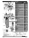
NOTE: The (22)fluid trackis acastassembly andcannot bedisassembled
forcleaning.Donot allowmaterialtosolidify insidetheheater.Flushthe
paint heater with the proper solvent immediately following each use.
CAUTION Shut the electrical supply off and relieve all pressure
from the system before servicing any part of the fluid heater system.
CLEANING
1. When cleaning the fluid heater, use only solvents compatible with the
material being pumped.
2. The fluidheatershouldbeflushedwith solventwhenchangingmedias,
or when it is not being used for a period of time.
NOTE: For other maintenance problems, see ``Trouble Shooting", page 4.
DISASSEMBLY
NOTE: The following procedure is for the repair of the (24) heater cartridge asĆ
sembly, (29) thermostat or the (23) cutoff assembly.
1. Relieve all fluid pressure in the system.
2. Rotate the (17) adjusting knob counterclockwise to the ``off" position.
3. Disconnect the power supply to the fluid heater assembly.
4. Disconnect the fluid lines.
5. Remove the six (2) cap screws.
6. Remove the (20) cover.
7. Remove the two (12) machine screws and (11) lockwashers from the
(21) housing, which retain the thermostat assembly.
8. Remove (as one unit) the(10) terminal block, (29) thermostat and(13)
mounting plate by carefully lifting it out and removing the power lead
wires (1and3)from thefirst twopositions onthe(10)terminalblock(reĆ
fer to figure 3).
9. Removethe(24)heatercartridgeassemblyleadsfromthe(10)terminal
block third and fourth positions.
10. Carefully finish removingthe assembly bypulling the thermostatcapilĆ
lary tube out of the (22) fluid track body.
NOTE: Specialcare mustbe takennot tosharplybend or kinkthe capillary tube
which will ruin the thermostat. Do not use pliers or other tools which may also
damage the tube.
11. Remove the(28) indicatorlamp leadsfrom the (10)terminal blockthird
and fourth positions.
12. Unscrew the (15) site plug to remove the (28) indicator lamp from the
assembly.
13. Removethe(23)cutoffassemblyleadsfromthe(10)terminalblocksecĆ
ond and fourth positions. Carefully remove the (23) cutoff assembly
from the (22) fluid track.
HEATER
CARTRIDGE REMOV
AL
1. Pull the (24) heater cartridge assembly from the (22) fluid track. NOTE: If the
(24) heater cartridge assembly does not easily come out, do the following:
a. Remove the (25) pipe plug from the bottom of the (22) fluid
track.
b. Carefully drive the (24) heater cartridge assemblyout thru the
top of the heater (toward the cover).
REASSEMBLY
1. Reassembly is done in the reverse order.
NOTE: Care must be taken to keep the (29) capillary tube away from the
(23) cutoff assembly.
NOTE: Whenreinstallingthe(20)cover,becertainthe(17)adjustingknobis
turnedout. Ifthe (18)screwisthreaded intoo far,itwillinhibitthe coverfrom
properly sealing flat against the housing.
2. Rotate the adjusting knob clockwise out as far as it will go and turn it
back in carefully to align the slots with the thermostat.
3. Apply Watt Lube to (24) heater cartridge assembly.
4. Apply DowCorning 340 Silicone HeatSink compound to the(29) therĆ
mostat probe and (23) cutoff assembly. This material increases the
overall efficiency of the devices.