


108604 10/08 12-25
WARNING: Never work under the machine or attachment unless it is safely supported with jack
stands. Make certain machine is secure when it is raised and placed on the jack stands. The jack
stands should not allow the machine to move when the engine is running and the drive wheels are
rotating. Use only certified jack stands. Use only appropriate jack stands, with a minimum weight
rating of 2000 pounds to block the unit up. Use in pairs only. Follow the instructions supplied with the
vehicle stands.
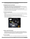
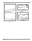
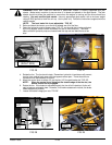
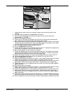
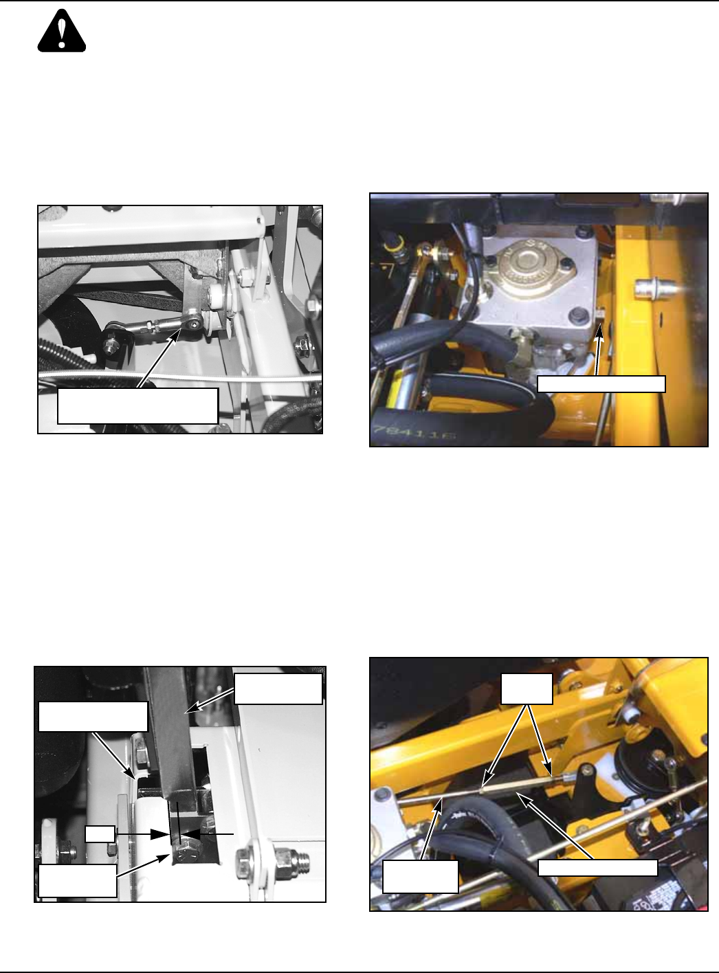
NOTE: The front brake link is not adjustable. "FIG. 26"
2. Raise and block the tractor up so the drive wheels are off of the floor.
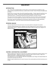
3. Open the hydraulic pump’s bypass valve "FIG. 27", on the side that is being adjusted,
by turning bypass valves counter clockwise one-half to one revolution. The valve
stems on each hydraulic pump are located near the top and are identified as a hex
stud.
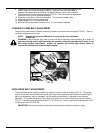
4. Rotate the tire. The tire should rotate. Remember hydraulic oil resistance will prevent
the tire from rotating freely even with the bypass valves open. There should be no
resistance from the brakes at this point.
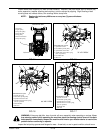
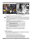
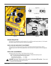
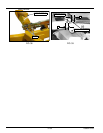
5. Move the control lever to where it is just inside (1/8”) the park brake slot "FIG. 28".
NOTE: When the control lever is against the outside edge of the the slot, the
brakes should not be engaged.
6. Rotate the tire. If the brake is adjusted properly the tire will still rotate but friction will
start to become noticeable here. However, if no brake resistance is noticed, the brake
needs adjusted as follows:
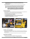
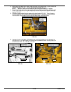
7. Loosen the brake linkage jam nuts "FIG. 29".
FIG. 26 FIG. 27
FIG. 28 FIG. 29
FRONT BRAKE LINK
(RIGHT SIDE)
BYPASS VALVE
OUTSIDE
EDGE
CONTROL
LEVER
PARK BRAKE
SLOT
1/8"
JAM
NUTS
TURNBUCKLE
BREAK
LINKAGE