


12-18 108604 10/08
Owners should be reminded that failure to use original equipment replacement parts is an “alteration” and
will not be considered for warranty in the event of engine damage.
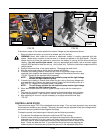
RECOMMENDED SERVICE PROCEDURE
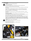
1. Release clamps and remove element. Clean the canister with a damp cloth.
2. Before installing a new element, inspect it by placing a bright light inside and rotate the element slowly,
looking for any holes or tears in the paper. Also check gaskets for cuts or tears. Do not attempt to use a
damaged element which will allow abrasive particles to enter the engine.
3. Reinstall the dust cup. Make sure it seals all the way around the air cleaner body, then tighten the clamps.
4. Check all fittings and clamps periodically for tightness and inspect hoses for holes or cracks.
5. Periodically check the intake hose for signs of ingested dust. Locate and repair the source of ingested dirt.
6. Never operate a machine without an air filter installed.
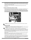
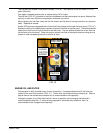
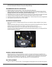
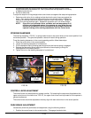
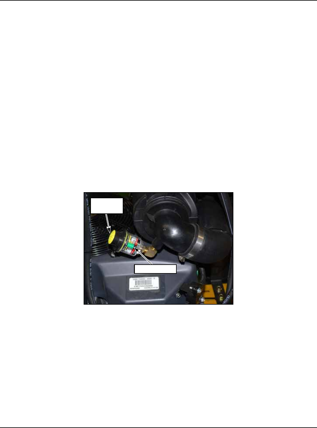
AIR RESTRICTION INDICATOR
Any unit with a Kohler or Kawasaki engine will have an air restriction indicator installed in the air cleaner
"FIG. 13".
Replace the element whenever the restriction indicator shows reaches the change filter red line. Check the
indicator daily and replace element as needed or annually whichever occurs first.
Reset the indicator by pushing in on the yellow button after each element change "FIG. 13"
A restriction indicator takes the guesswork out of air cleaner servicing and allows you to safely benefit from
the filter’s optimum performance.
GENERAL ENGINE MAINTENANCE
Detailed instructions and recommendations for break-in and regular maintenance are specified in the
Engine Owner’s manual. Please refer to this manual for engine servicing, lubricating oil levels with quality
and viscosity recommendations, bolt torques, etc. The engine warranty is backed by the manufacturer.
Special attention should be paid to applicable data which will not be duplicated here.
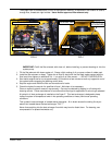
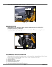
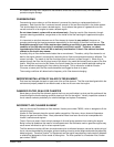
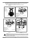
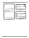
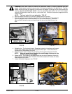
BELT REPLACEMENT
"FIG. 14", "FIG. 15", "FIG. 16" & "FIG. 17" show diagrams and descriptions of the unit’s belt drive systems.
FIG. 13
INDICATOR
RESET
BUTTON