


601457_1107 21
Wear gloves when handling blades. Always check for blade damage if
mower strikes rock, branch or other foreign object during mowing!
Mower blade removal
Use a 15/16" wrench to remove the 5/8" cap screw holding the blade to
the spindle shaft from underneath. NOTE: A blade holding tool (part num-
ber 381442) is available from Hustler Turf Equipment. It is designed to pre-
vent the blades from rotating when they are being removed or installed on
the spindle. Contact your Hustler dealer for more information.
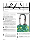
Sharpen the blades on a grinder following pattern as shown (Fig. 4-6).
Touch-up sharpening can be done with a file.
Check the blades for balance following grinding. A commercial balanc-
ing tool is available through most hardware supply stores, or balancing can
be done by placing the blade on an inverted line punch or 5/8" bolt. Blade
should not lean or tilt. Spin the blade slowly, blade should not wobble. If
blade is out of balance, true it up before reinstalling.
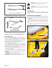
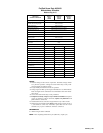
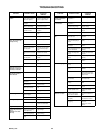
Lay the blade on a flat surface and check for distortion (Fig. 4-7 and 4-
8). Replace any distorted blade.
Do not re-use spindle bolts which have stripped, worn or undercut
threads. Torque bolts on spindles to 118 foot-pounds (160.01nm) when rein-
stalling blades.
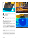
IMPORTANT: The blade sail (curved part) must be pointing upward
toward the inside of the deck to ensure proper cutting.
IMPORTANT: When mounting blades, rotate them after installation to
ensure blade tips do not touch each other or sides of the mower.
WARNING: Failure to correctly torque the bolt may result in
the loss of the blade which can cause serious injury.
WARNING: Mower blades are sharp and can cut. Wrap the
blade(s) or wear gloves and use extra caution when servicing
them.
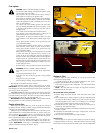
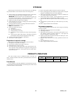
Seat adjustment
The seat can be adjusted forward and rearward by sliding the seat release
handle and moving the seat until a comfortable operating position is attained.
Fig. 4-19
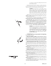
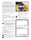
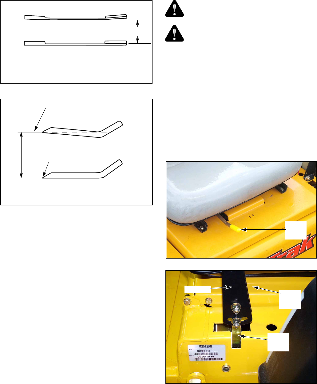
Steering control lever adjustment
The steering control levers can be adjusted for operator comfort. By
loosening the cap screws that attaches the upper control lever to the lower
lever (Fig. 4-10), the upper control lever can be pivoted to fit the operator’s
personal preference.
The steering control levers can also be adjusted up and down. Remove
the cap screws and slide the upper control lever up or down and align the
holes in it with the holes in lower lever. Re-install the cap screws and
tighten.
The steering control levers should be adjusted so that they align with
each other when in the neutral position.
Figure 4-8
Cutting edge
Cutting edge
Twisted Blade Edge
(replace)
Straight Blade Edge
End view of blades, comparing
twisted and straightened blades
Cutting Plane
Figure 4-7
Warped Blade (Replace)
Warped Blade (Replace)
Comparison of Warped and Straight Blades
Cutting
plane
Seat
release
handle
Figure 4-9
Figure 4-10
Upper
control
lever
Lower
control
lever
Cap screw