


601457_1107 15
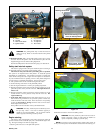
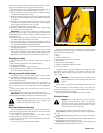
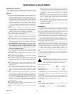
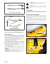
WARNING: Never direct discharge of material from mower
deck towards bystanders. Do not operate the mower without
either the discharge chute or the entire grass collection system
in place. Fig. 3-9
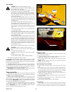
Mower deck operation
DANGER: Never attempt to make any adjustments to the
mower deck while the engine is running or with the deck drive
clutch engaged. Mower blades cannot be seen and are located
very close to deck housing. Fingers and toes can be cut off
instantly.
With the engine running, engage the deck clutch switch (Fig. 3-1A & 3-
1B) and advance engine throttle to full rpm.
NOTE: Engaging the deck clutch at high engine rpm or when under
heavy load (in tall grass for example) can cause belts and/or electric clutch to
slip, resulting in premature wear or possible damage.
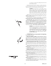
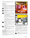
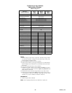
Deck cutting height adjustment
Deck height is adjustable from 1-1/2” to 4-1/2” (3.81 cm - 11.43 cm) in
1/4” increments. The holes in the height adjusting bar are spaced at 1/2”
intervals. By turning the height adjusting stop around, 1/4” increments can
be attained due to the 1/4” plate that is part of the stop. Fig. 3-11
EXAMPLE: When the height adjusting stop is placed in the 1-1/2” (3.81
cm) hole, with the 1/4” (.64 cm) plate facing to the front of the unit, the
cutting height is at 1-1/2” (3.81 cm). When the height adjusting stop is placed
in the 1-1/2” (3.81 cm) hole, with the 1/4” (.64 cm) plate on the operator’s
side of the hole, the cutting height is at 1-3/4” (4.45 cm).
The notch located at the rear of the height adjusting bar is to be used
when the deck is placed in the transport mode.
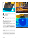
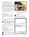
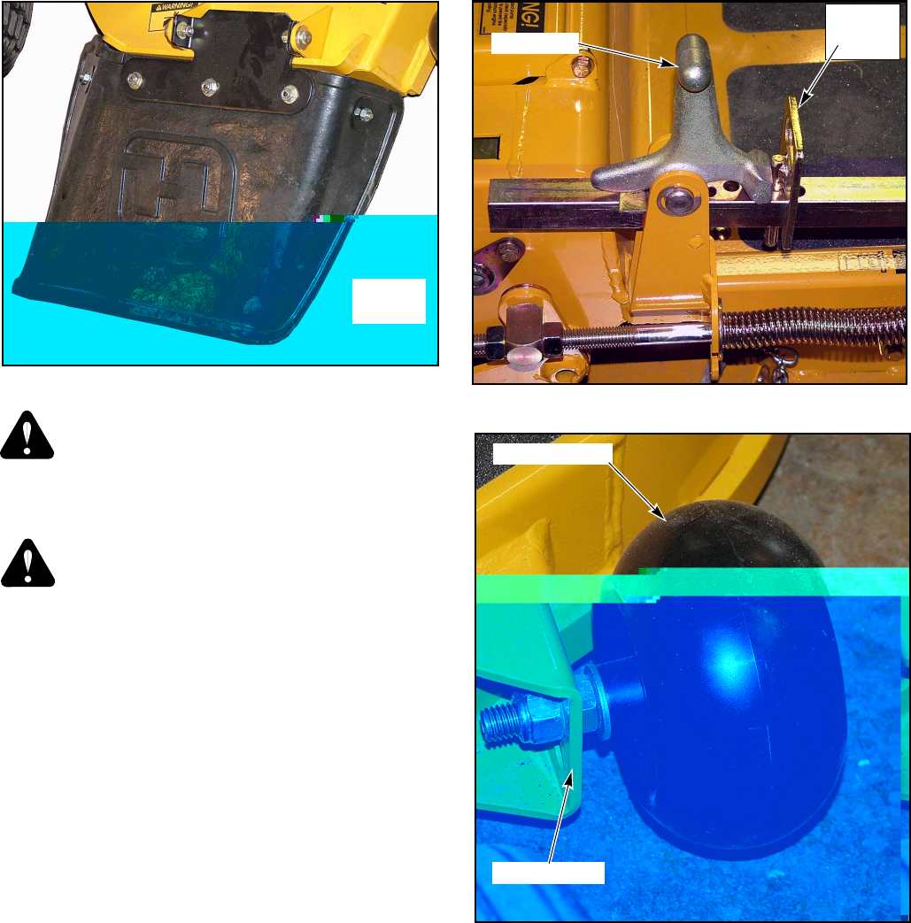
Anti-scalp wheels
Anti-scalp wheel kits are standard on FasTrak Super Duty units. These
anti-scalp wheels are designed to minimize scalping when mowing on rough
uneven terrain.
After setting the cutting height, adjust the anti-scalp wheels so they
extend below the deck but do not contact the ground. They should always
be at least 1/4” to 3/4” (6.35mm to 19.05mm) below the deck. With the unit
sitting on a flat level surface, the wheel position can be adjusted up or down
as needed from 3/4” to 1-3/4” (19.05mm to 44.45mm) below the blade sur-
face. Move the wheels up or down, in 1/2” (12.70mm) increments, using the
different axle mount holes in the wheel mount bracket. Fig. 3-11
When adjusting the rear anti-scalp wheels, the wheel should be in the
same axle mount hole as the front anti-scalp wheels.
Figure 3-10
Stop handle
Height
adjusting
stop
Figure 3-9
Side
discharge
chute
Figure 3-11
Anti-scalp wheel
Adjusting holes